AC
JGX-5F-MY
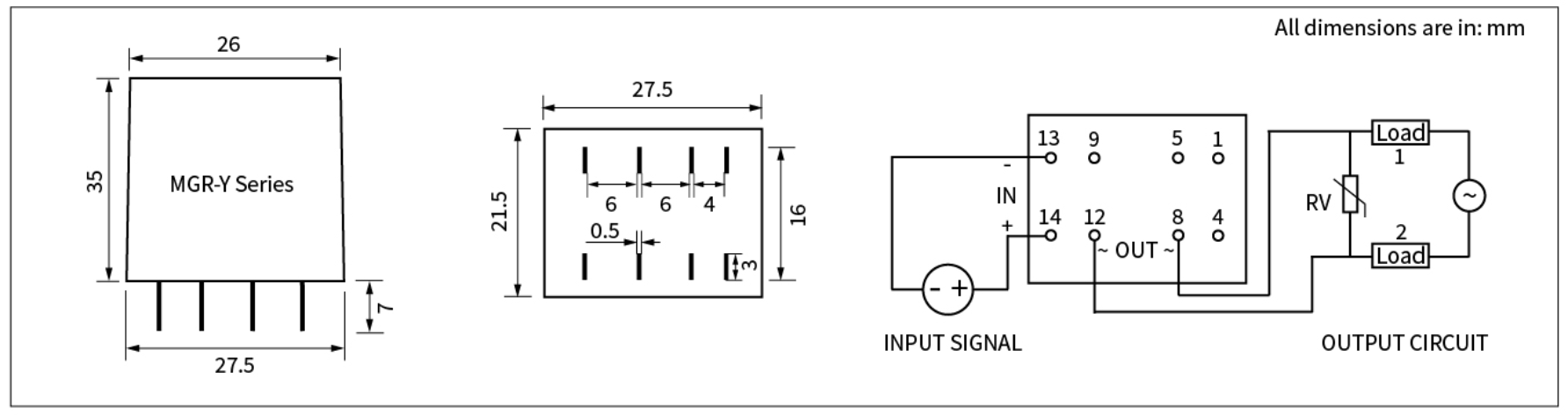
Control: 14 (+), 13 (−). AC output: 8 (~), 12 (~). The original drawing shows the other pin positions for orientation.

DIP-8 / PLUG-IN / DC CONTROL
Eight pins.
AC or DC output.
Two output choices in a compact eight-pin format. Compare the load voltage and terminal polarity before choosing your relay.
Compare specifications ↗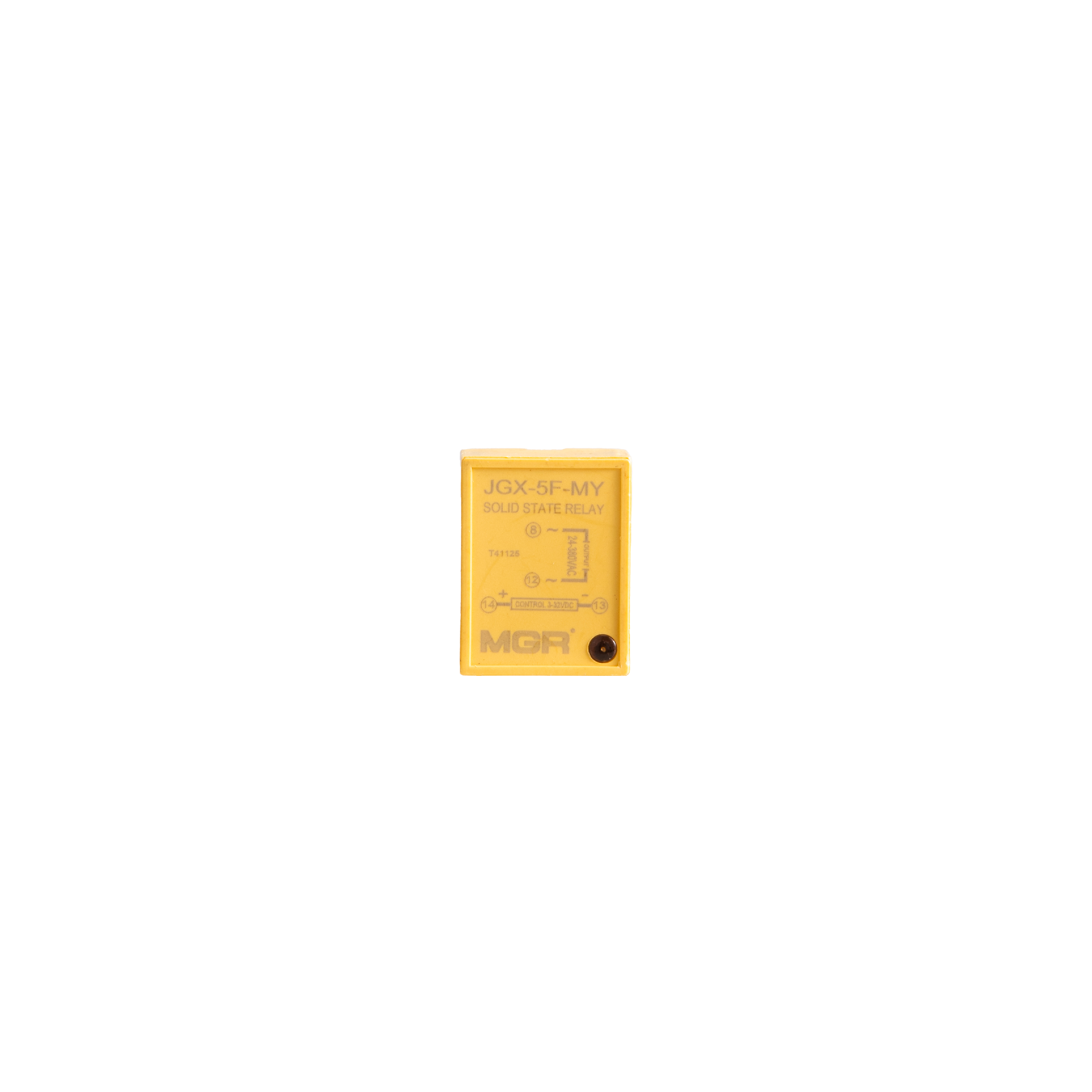
24–380 V AC
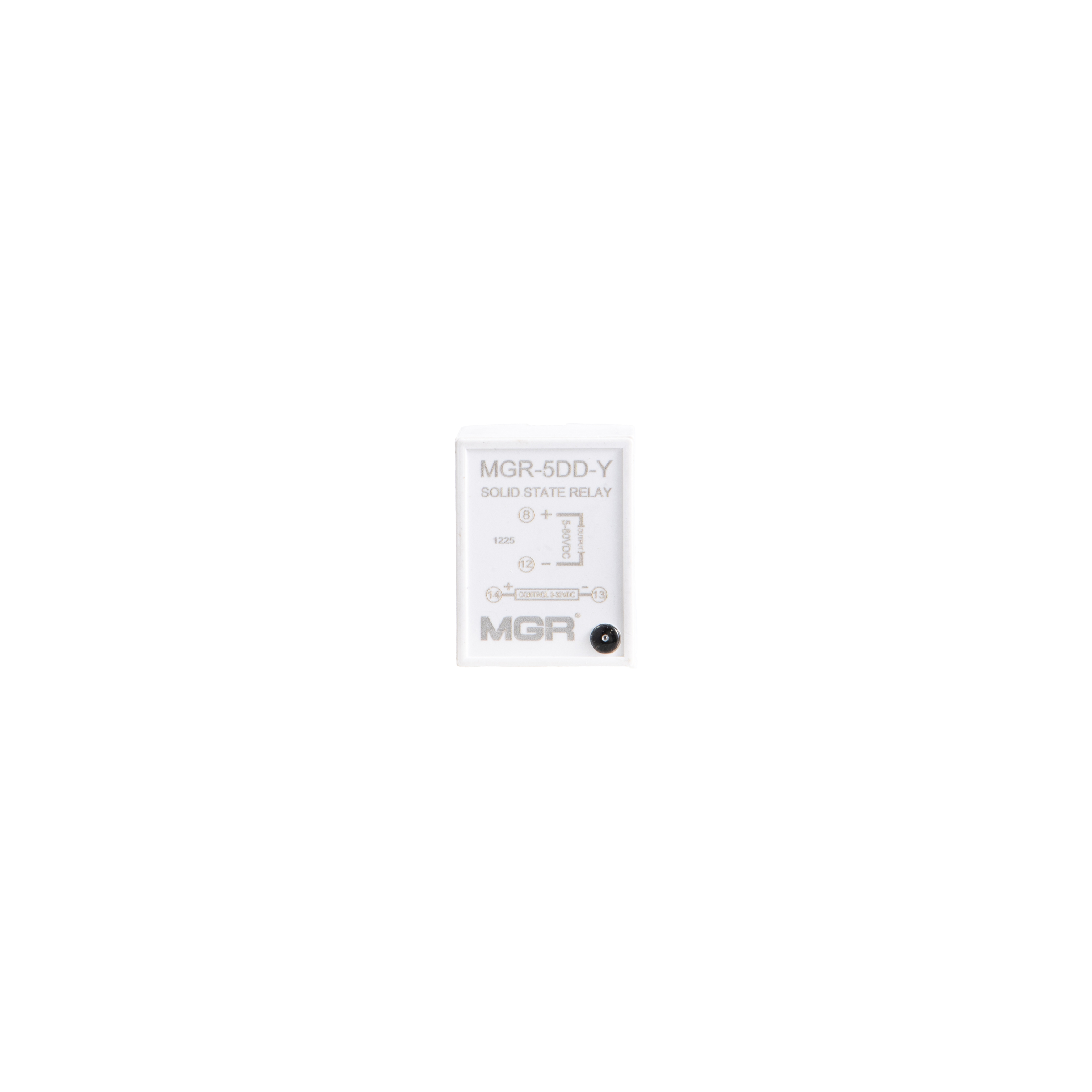
5–60 V DC
Eight-pin solid state relays with separate control and load connections. Both illustrated products are marked 5 A. Choose the AC-output or DC-output version to suit the actual load supply.
| Parameter | JGX-5F-MYAC OUTPUT | MGR-5DD-YDC OUTPUT |
|---|---|---|
| Models shown / listed | JGX-5F-MY | MGR-5DD-Y |
| Control voltage | 3–32 V DC | 3–32 V DC |
| Control current | ≤10 mA | ≤10 mA |
| Load voltage | 24–380 V AC | 5–60 V DC |
| Current versions | 5 A illustrated; family options: 1 / 3 / 5 A | 5 A illustrated; family options: 1 / 3 / 5 A |
| Package | DIP-8 | DIP-8 |
| Output polarity | AC output: no DC polarity | DC output: observe + / − |
Select voltage and current together. Series-level options do not mean every housing or model has every rating. Confirm the actual relay label when ordering.
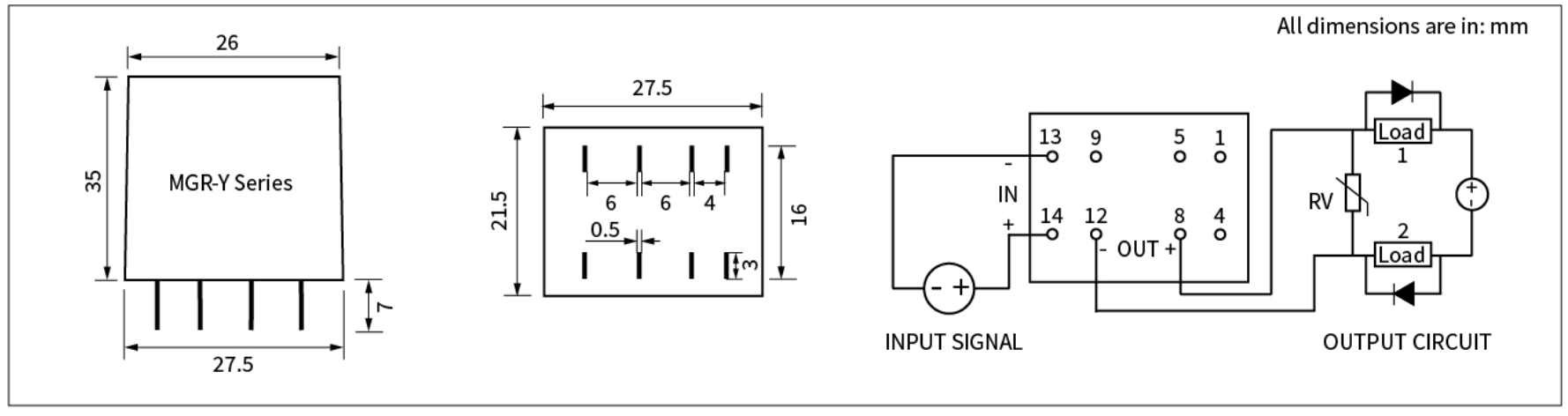
Use the complete original drawing to check the 6 / 6 / 4 mm pin spacing and terminal orientation. Do not infer electrical connections for the other pins.
Control: 14 (+), 13 (−). AC output: 8 (~), 12 (~). The original drawing shows the other pin positions for orientation.
Control: 14 (+), 13 (−). DC output: 8 (+), 12 (−). Verify the bottom-view orientation and the markings on the actual relay before connecting.
Match the relay output to the load supply. Do not substitute an AC-output relay for a DC-output relay.
Confirm current, inrush, voltage and enclosure temperature for the application. Allow adequate PCB electrical spacing and heat dissipation.
Resolve the drawing differences above before committing a PCB footprint or socket. Ask MGR to confirm the exact model and housing.
Technical reference: Company JGX-5F-MY and MGR-5DD-Y parameter sheets and original size/circuit drawings. Numeric isolation, leakage current, switching time and derating values are not assumed where the supplied material does not specify them.
PCB SOLID STATE RELAYS