AC
GJ-L
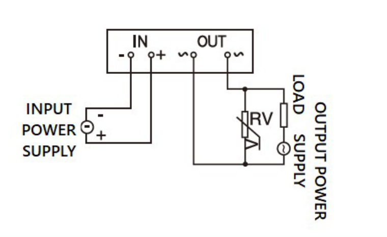
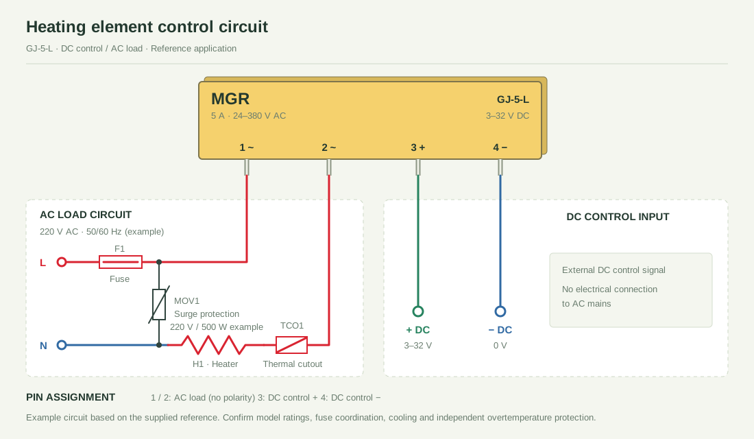
Connect the AC supply, load and relay output in series. Terminals 1 ~ and 2 ~ have no DC polarity.

SIP-4 / PCB MOUNT / DC CONTROL
A compact footprint.
AC or DC switching.
Two output types in the same single-in-line package. Choose the relay for your load, without changing the enclosure size.
Compare the two series ↗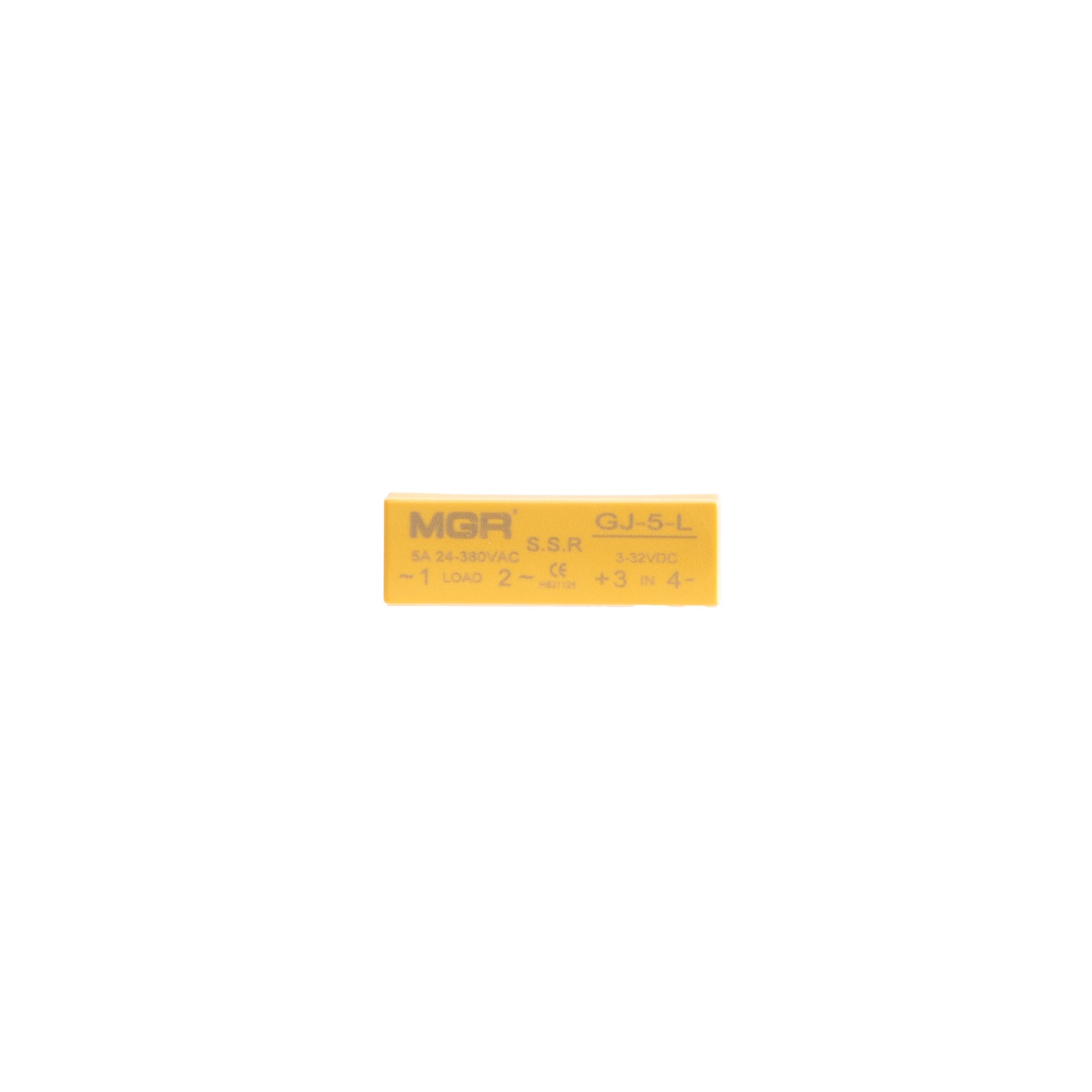
220 / 380 V AC · 1 / 3 / 5 A
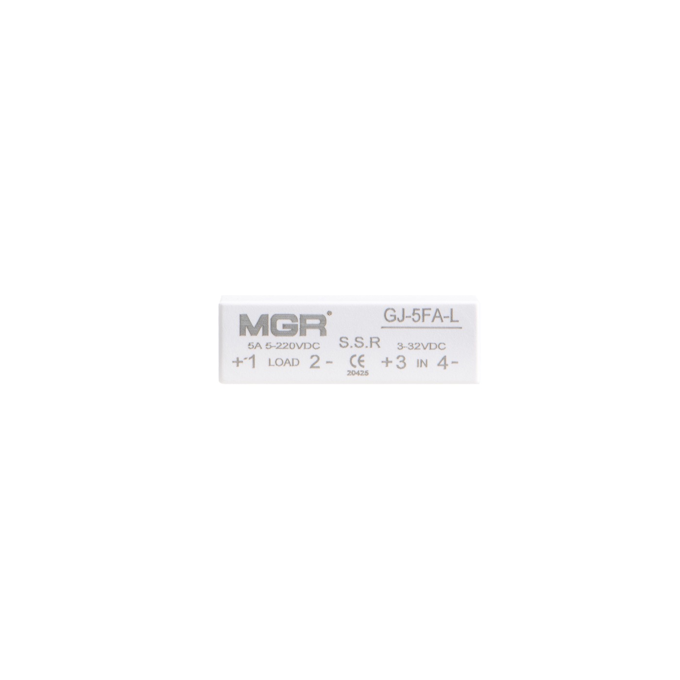
5–220 V DC · 1 / 3 / 5 A
Designed for direct PCB mounting, the GJ family uses four pins in a single row. Both versions share a plastic enclosure, low control-current requirements and a compact board footprint.
DC control for AC loads, with a standard output RC snubber circuit.
Low-impedance MOSFET output helps reduce output power consumption.
Low off-state leakage and low on-state voltage drop, as described in the datasheets.
A 38.5 mm enclosure length and single-row pins suit compact appliance and control boards.
The series catalogue lists 1 A, 3 A and 5 A versions for both output types. The photographs show the 5 A examples: GJ-5-L and GJ-5FA-L.
| Parameter | GJ-LAC OUTPUT | GJ-FA-LDC OUTPUT |
|---|---|---|
| Control / load | DC → AC | DC → DC |
| Reference model | GJ-5-L | GJ-5FA-L |
| Rated-current options | 1 / 3 / 5 A | 1 / 3 / 5 A |
| Load voltage | 220 / 380 V AC | 5–220 V DC |
| Control voltage | 3–32 V DC | 3–32 V DC |
| Control current | ≤10 mA | ≤10 mA |
| Output design | AC switching · RC snubber | Low-impedance MOSFET |
| Load terminals | 1 ~ / 2 ~ | 1 + / 2 − |
| Control terminals | 3 + / 4 − | 3 + / 4 − |
| Mounting / package | PCB mount · SIP-4 | PCB mount · SIP-4 |
| Housing dimensions | 38.5 × 22 × 12.5 mm | 38.5 × 22 × 12.5 mm |
AC voltage follows the PDF specifications (220 / 380 V AC). The illustrated GJ-5-L is marked 24–380 V AC. Confirm the exact voltage range on the selected model label before use.
5 = 5 A · FA = DC output · L = Single-in-line package.
Examples: GJ-5-L (AC output) / GJ-5FA-L (DC output).
Shared housing size: 38.5 × 22 × 12.5 mm. The original PDF drawing shows 10 / 12 / 5 mm adjacent pin spacing, four Ø0.8 mm pins and a 10 mm pin extension. Dimensions below are in millimetres.
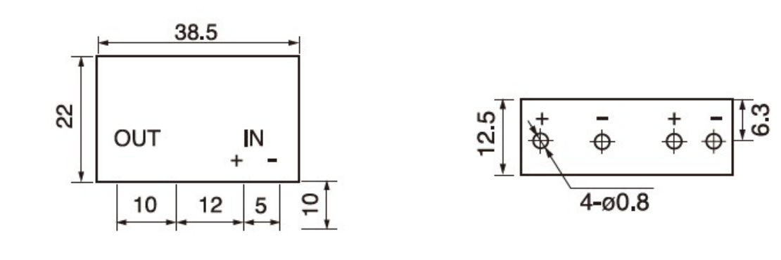
Both types use terminals 3 (+) and 4 (−) for the DC control input. The load connects through terminals 1 and 2; output polarity depends on the selected relay.
Connect the AC supply, load and relay output in series. Terminals 1 ~ and 2 ~ have no DC polarity.
Connect supply + → load → 1 (+), then 2 (−) → supply −. Observe the DC output polarity.
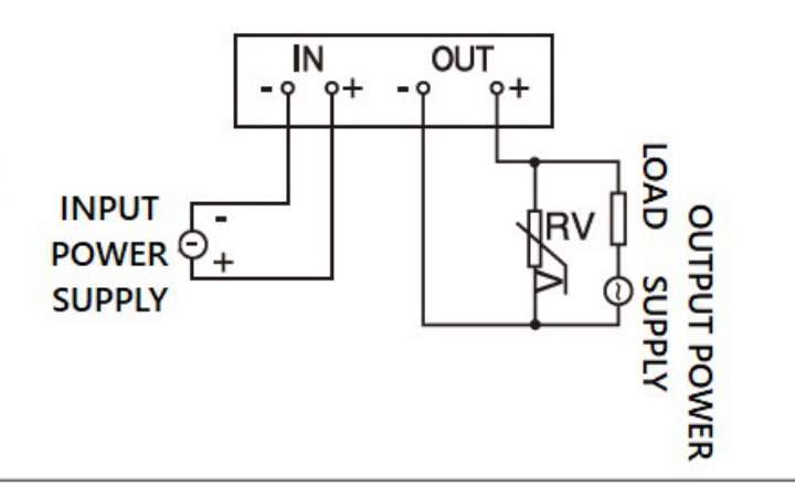
The product PDFs identify air conditioners, balers and household appliances as typical applications. Select AC or DC output to match the load supply, then confirm voltage, operating current and inrush requirements.
Use GJ-L for AC switching and GJ-FA-L for DC switching. Do not substitute one output type for the other.
Confirm the selected 1, 3 or 5 A version against the actual load and board temperature. The supplied PDFs do not give a thermal derating curve or numeric inrush rating.
Allow for heat dissipation, suppression and PCB electrical spacing. Verify the exact model label, pin orientation and supplied drawing before powering the board.
Technical reference: supplied GJ-5-L and GJ-5FA-L product PDFs and GJ Series SIP-4 catalogue. Numeric leakage current, voltage drop, switching time and isolation test ratings are not specified in these documents and are not assumed here.
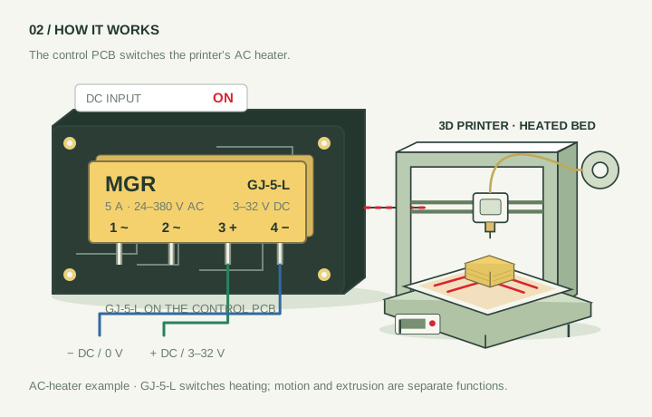
GJ-5-L AC-output example: an independent DC command switches the AC heater. The example supply is 220 V AC and the example heater is 500 W; these are application conditions, not additional relay ratings.
SIP-4 PCB SOLID STATE RELAYS