AC
JGX-1F(5A)
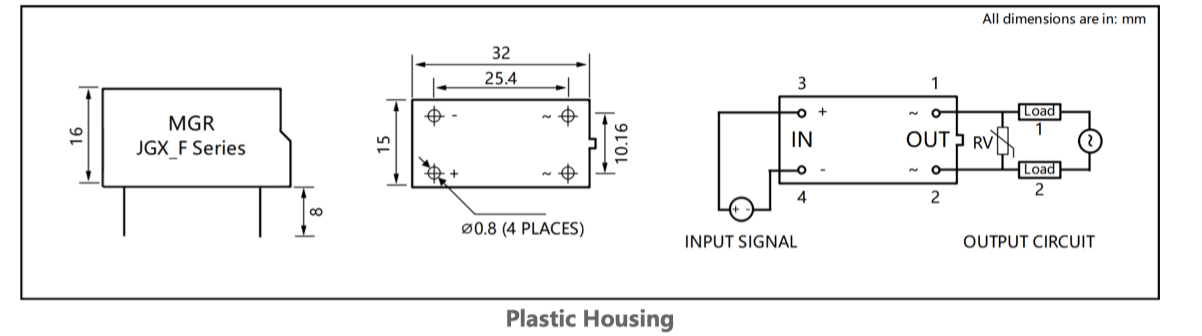
Control: 3 (+), 4 (−). AC output: 1 (~), 2 (~). Connect the load and AC supply in series with the output.

DIP-4 / PCB MOUNT / DC CONTROL
Small footprint.
Two ways to switch.
A paired family for AC and DC loads. Compare the two output types side by side, then confirm the housing and pin layout for your board.
Compare specifications ↗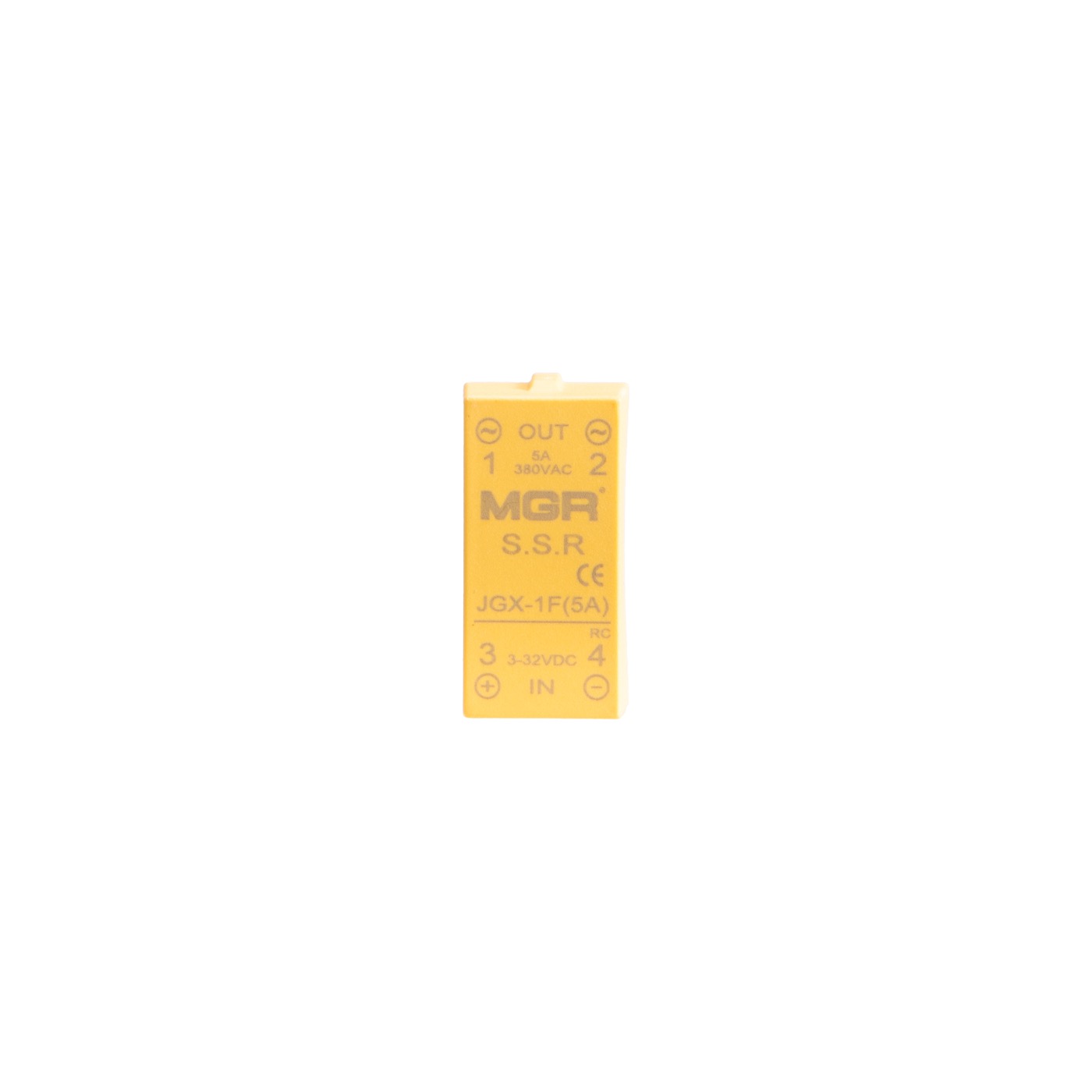
220 / 380 V AC
5–220 V DC
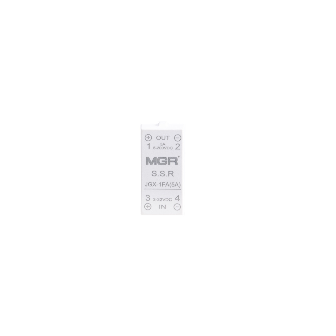
Four-pin relays for board-level switching. Yellow identifies the AC-output version shown here; white identifies the DC-output version. The 5 A product photographs are examples, not a shared rating for every model.
| Parameter | JGX-1F(5A)AC OUTPUT | JGX-FADC OUTPUT |
|---|---|---|
| Models shown / listed | JGX-1F(5A) | JGX-1FA · JGX-3FA · JGX-5FA · JGX-8FA |
| Control voltage | 3–32 V DC | 3–32 V DC |
| Control current | ≤10 mA | ≤10 mA |
| Load voltage | 220 / 380 V AC | 5–220 V DC |
| Current versions | 5 A illustrated; plastic family: 1 / 3 / 5 A | 1 / 3 / 5 A plastic; 5 / 8 A integrated heat-sink versions |
| Package | DIP-4 | DIP-4 |
| Output polarity | AC output: no DC polarity | DC output: observe + / − |
Select voltage and current together. Series-level options do not mean every housing or model has every rating. Confirm the actual relay label when ordering.
The catalogue also lists metal and integrated heat-sink housings. Their dimensions and footprints are not interchangeable with the plastic version.
Control: 3 (+), 4 (−). AC output: 1 (~), 2 (~). Connect the load and AC supply in series with the output.
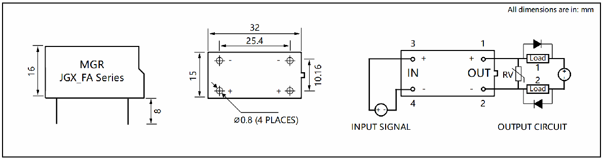
Control: 3 (+), 4 (−). DC output: 1 (+), 2 (−). Observe polarity and use the original DC circuit below.
Match the relay output to the load supply. Do not substitute an AC-output relay for a DC-output relay.
Confirm current, inrush, voltage and enclosure temperature for the application. Allow adequate PCB electrical spacing and heat dissipation.
Resolve the drawing differences above before committing a PCB footprint or socket. Ask MGR to confirm the exact model and housing.
Technical reference: JGX catalogue, PDF pages 7–11, and company product-folder materials. Numeric isolation, leakage current, switching time and derating values are not assumed where the supplied material does not specify them.
PCB SOLID STATE RELAYS