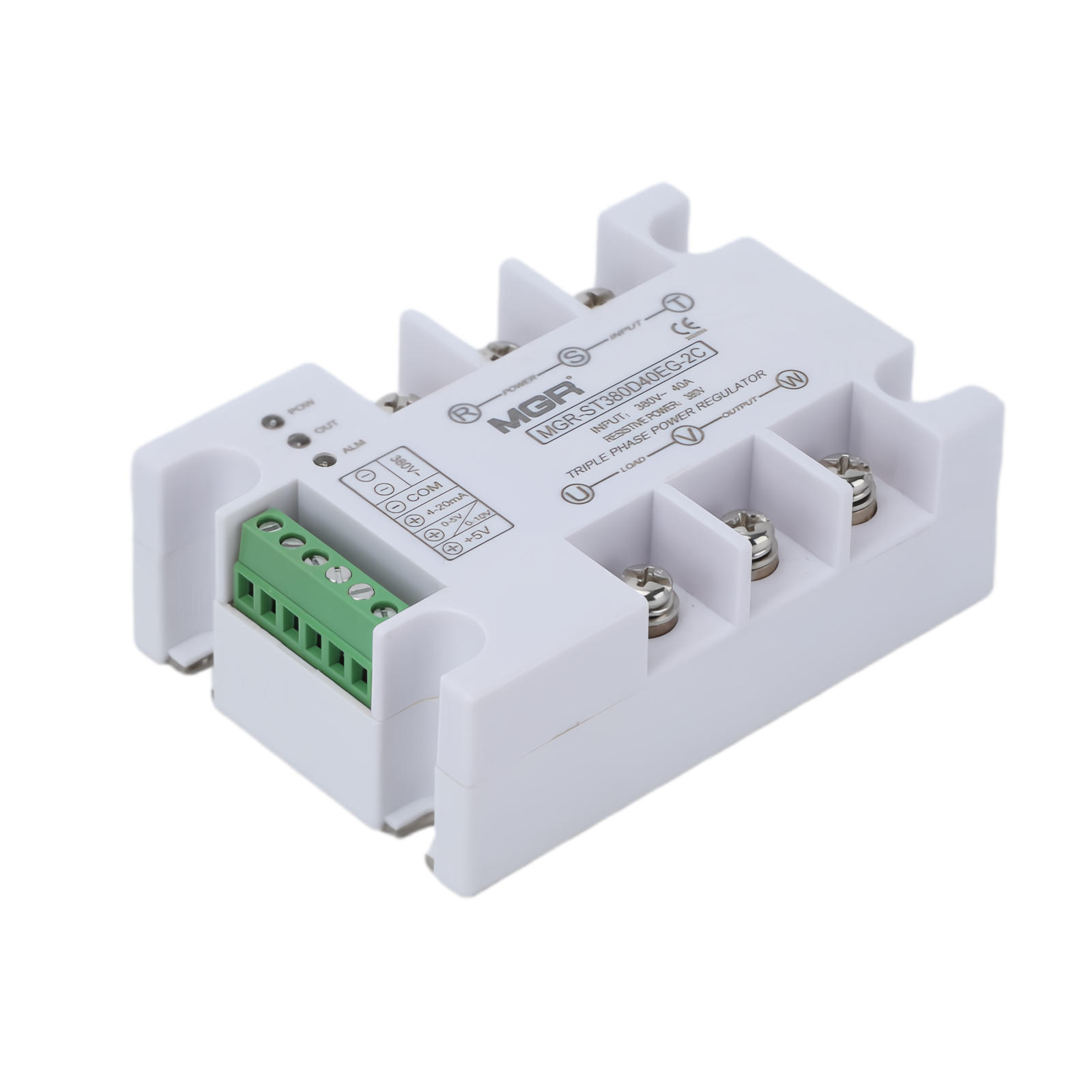
← All power regulators

PANEL MOUNT / THREE-PHASE / VOLTAGE REGULATOR

MGR-ST
Series

Integrated three-phase voltage control for industrial heating and process equipment. Isolated signal inputs, soft start and clear operating indicators in one panel-mount module.

Ask about this series ↗
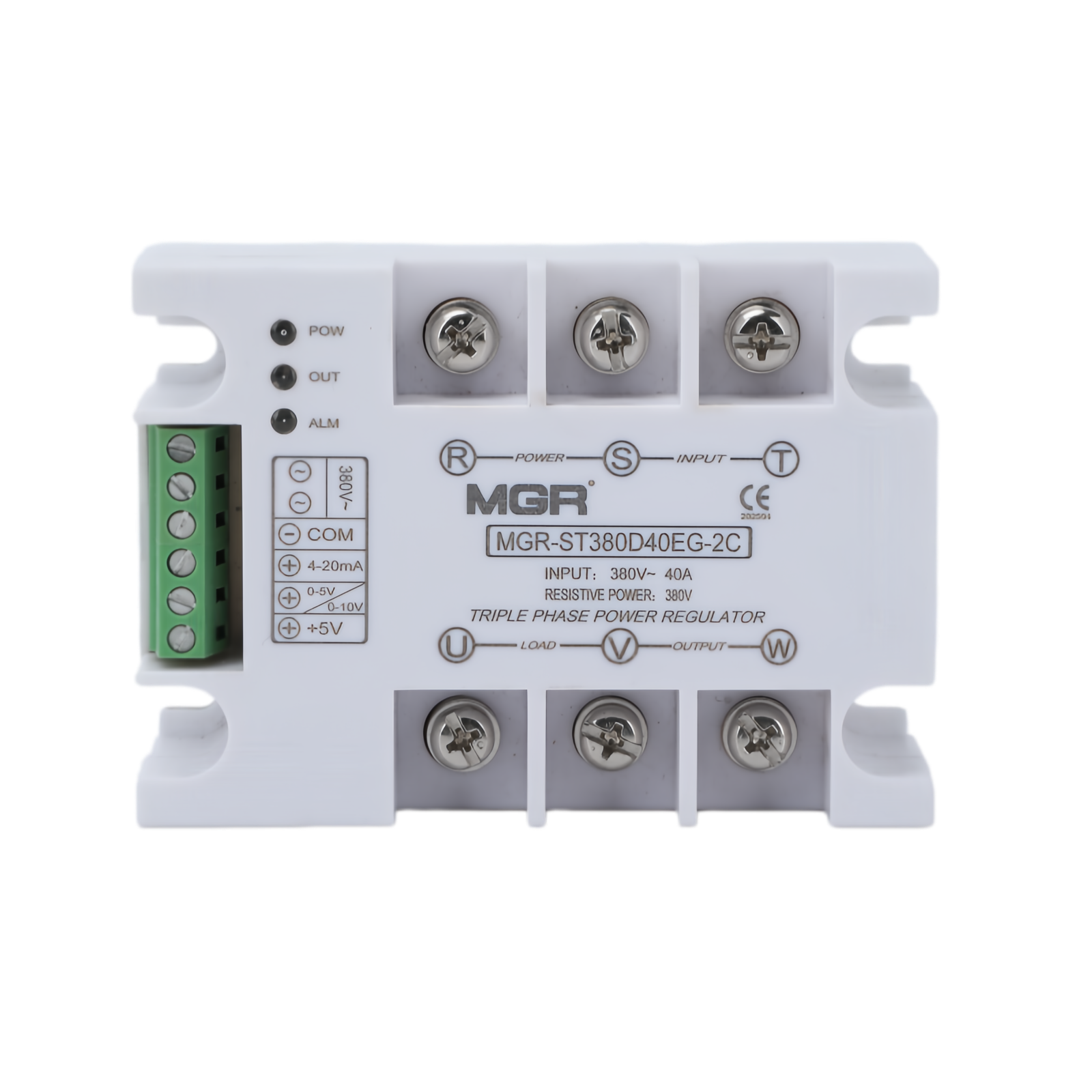
MGR-ST380D40EG-2C front view
MGR-ST380D40EG-2C · Front view
01 / CONTROL & SELECTION

Three phases.
One compact module.

The MGR-ST integrates synchronization and control circuitry, with no external synchronization transformer required. Versions with a 220 V AC or 380 V AC auxiliary supply are available; a version requiring no separate external auxiliary power supply is available on request. Power-on soft start helps reduce the initial current surge. Over-temperature and phase-loss indicators support operating checks.

380 V ACThree-phase main circuit
Isolated control4–20 mA · 0–5 V DC · 0–10 V DC
Soft startWith status and alarm indication
Series designationMGR-ST380D--EG-2C
Current code --25 / 40 / 60 / 80 / 100 / 120 A
Reference productMGR-ST380D40EG-2C · 40 A maximum rated load current
02 / PRODUCT VIEWS

See every side.

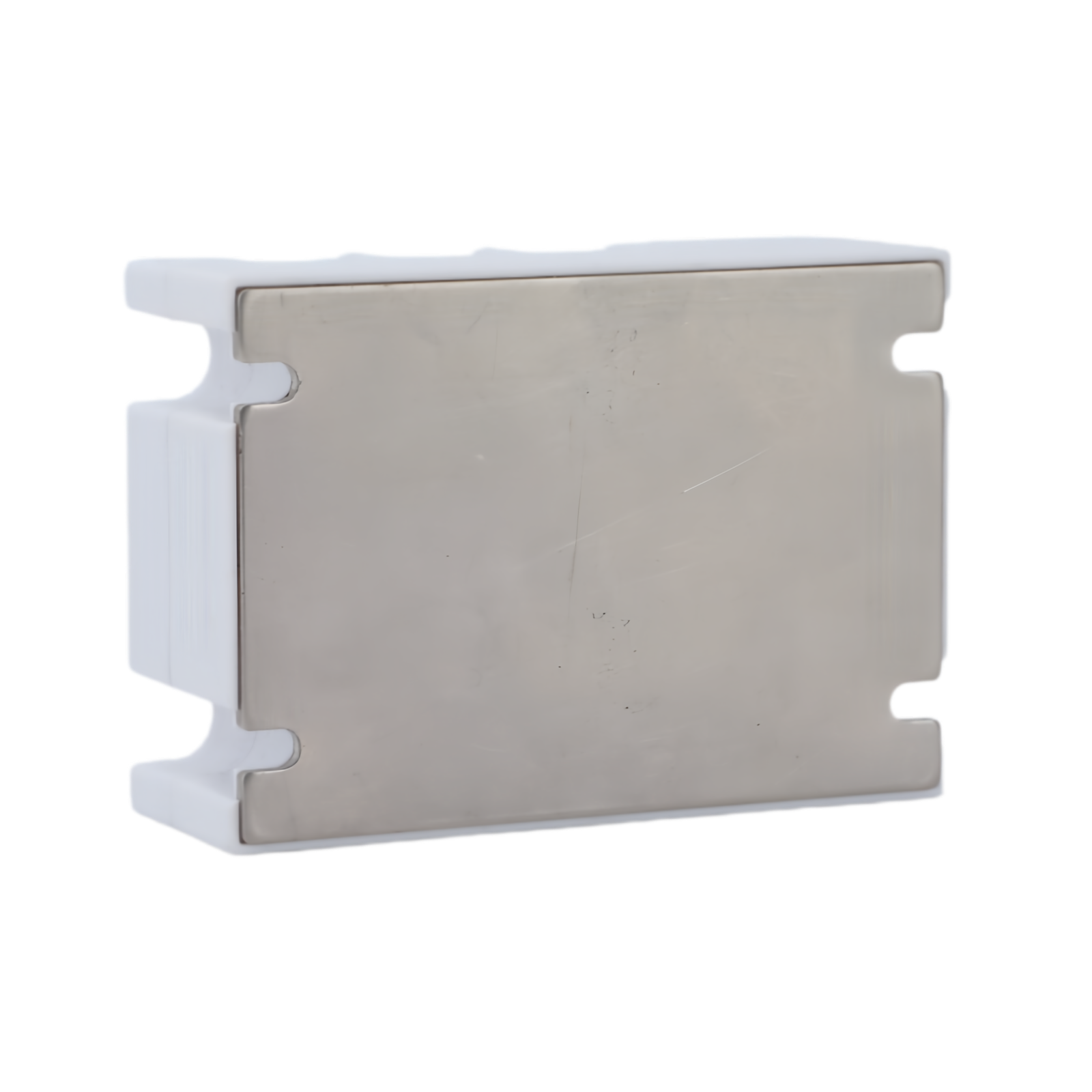
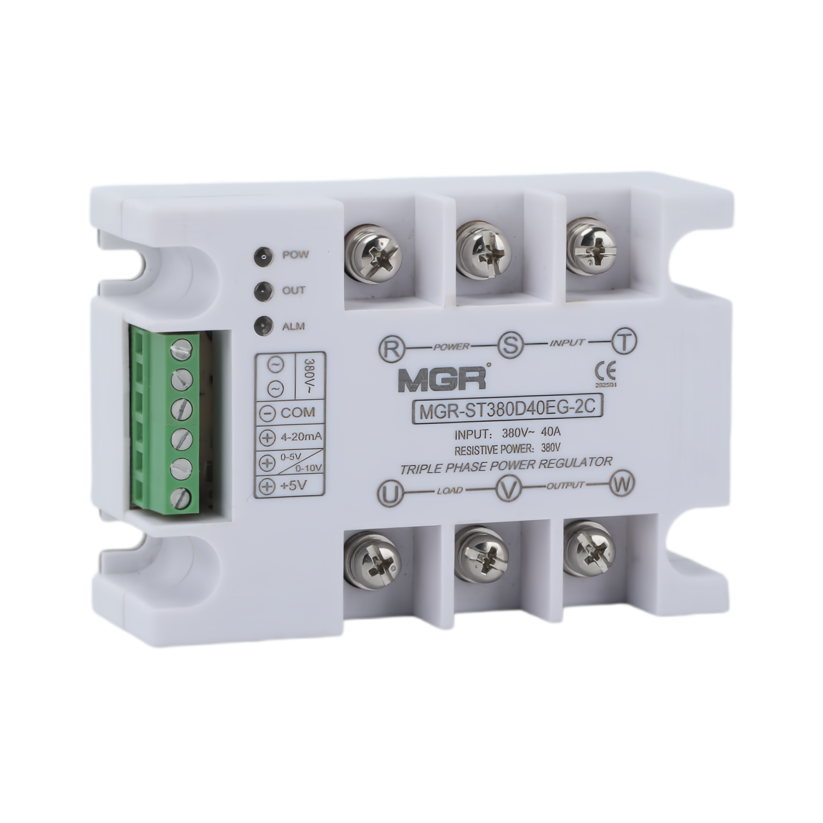
MGR-ST380D40EG-2C, with screw terminals, signal connections and a metal mounting base.
MGR-ST380D40EG-2C front
01 · Front
MGR-ST380D40EG-2C three-quarter
02 · Three-quarter
MGR-ST380D40EG-2C terminal view
03 · Terminal view
MGR-ST380D40EG-2C mounting base
04 · Mounting base
03 / PARAMETERS

Electrical reference.

Product typeFully isolated three-phase AC voltage regulator
Reference modelMGR-ST380D40EG-2C
Maximum rated load current — pictured model40 A
Main-circuit rated voltage380 V AC ±10%
Control methods4–20 mA / 0–5 V DC / 0–10 V DC; specify the required signal when ordering
Auxiliary supply220 V AC / 380 V AC options; specify when ordering
Custom supply optionVersion requiring no separate external auxiliary power supply available on request
Off-state leakage current<10 mA
Power input / load outputR, S, T / U, V, W
Phase sequenceNo phase-sequence requirement
Starting functionPower-on soft start
Alarm functionsOver-temperature and phase-loss indication
Status indicatorsPOW / OUT / ALM
Peak off-state voltage≥1200 V peak
Static / commutating dv/dt>200 V/µs
Response time / turn-off delay10 ms / 10 ms
Operating temperature0°C to +55°C
Overall dimensions106 × 75 × 38 mm
Mounting centres91 ±0.1 mm × 47 ±0.1 mm
04 / DIMENSIONS

Designed for your panel.

Overall dimensions: 106 × 75 × 38 mm. Mounting centres: 91 ±0.1 × 47 ±0.1 mm. All dimensions are in millimetres.
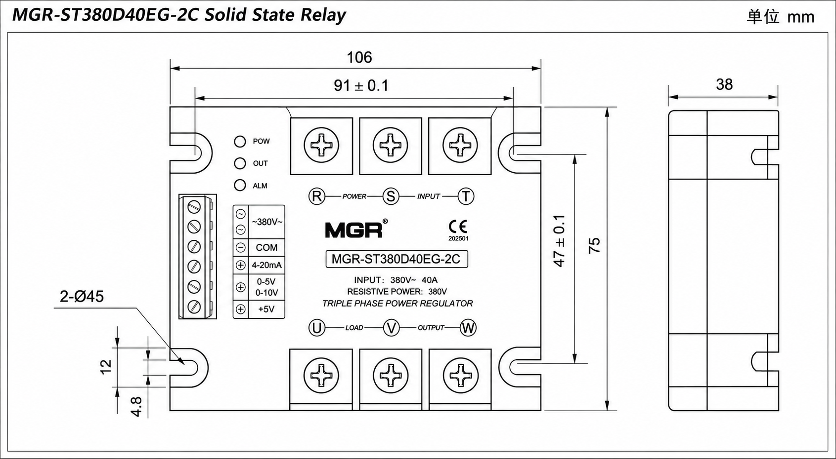
MGR-ST dimensional drawing showing 106 by 75 by 38 mm
MGR-ST380D40EG-2C · Select the drawing to view full size.
05 / WIRING & INSTALLATION

Connect. Control. Cool.

Connect the three-phase supply to 1 / 3 / 5 (R / S / T) and the load to 2 / 4 / 6 (U / V / W). Star and delta loads are supported. For an unbalanced star-connected load, connect the load neutral as specified in the installation instructions.
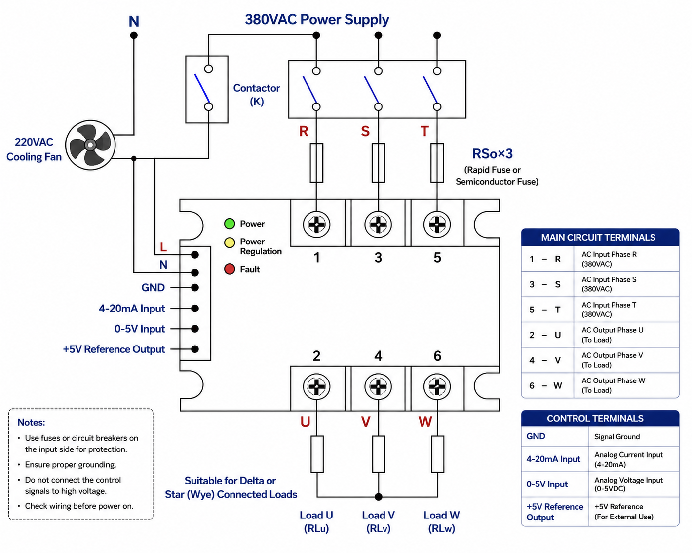
MGR-ST wiring reference for the 220 V AC auxiliary-supply version
220 V AC auxiliary-supply version only. For the 380 V AC version, follow its supplied wiring diagram and terminal markings. Select to view full size.
06 / MEASURED RESPONSE

From signal to output.

Measured transfer characteristic for MGR-ST380D40FG-2C. These results describe the tested unit, not every MGR-ST variant or the EG unit pictured above. Confirm the control range of your ordered model.

0–1.4 V DCMeasured dead zone
≈0.7 V ACResidual reading in the dead zone
1.5 V DC → 35 V ACFirst clear output rise
MGR-ST380D40FG-2C measured transfer curveDead zone 0 to 1.4 V DC, approximately 0.7 V AC residual output. At 1.5 V DC output rises to 35 V AC, reaching 375 V AC at 10 V DC. All 21 measurements are available in the data table.01002003004000246810Output (V AC)Control input (V DC)0 V DC → 0.7 V AC1 V DC → 0.7 V AC1.2 V DC → 0.7 V AC1.4 V DC → 0.7 V AC1.5 V DC → 35 V AC2 V DC → 60 V AC2.5 V DC → 83 V AC3 V DC → 110 V AC3.5 V DC → 140 V AC4 V DC → 170 V AC4.5 V DC → 200 V AC5 V DC → 237 V AC5.5 V DC → 269 V AC6 V DC → 298 V AC6.5 V DC → 320 V AC7 V DC → 338 V AC7.5 V DC → 350 V AC8 V DC → 360 V AC8.5 V DC → 365 V AC9 V DC → 370 V AC10 V DC → 375 V ACDead zone0–1.4 V1.5 V DC → 35 V AC
21 original measurements · Straight lines connect measured points.

The source identifies the approximately 0.7 V AC residual reading as induced voltage. The response is not linear across the measured range; do not assume half of the control voltage produces half of the output voltage.

Test reference only. Load, ambient temperature, instrument and test date are not specified in the supplied record. This curve is not a guaranteed tolerance specification.

View all 21 measurements
Control input (V DC)Output voltage (V AC)
00.7
10.7
1.20.7
1.40.7
1.535
260
2.583
3110
3.5140
4170
4.5200
5237
5.5269
6298
6.5320
7338
7.5350
8360
8.5365
9370
10375
Download measurement data (CSV) ↗
07 / APPLICATIONS

Built for industrial processes.

Electric furnaces, injection moulding, thermoforming, infrared heating, textile machinery and drying systems. For motors, transformers and other inductive loads, share your application details so MGR can confirm the appropriate regulator and current margin.

SELECT YOUR THREE-PHASE REGULATOR

Tell us about your load and control signal.

sales@mgrssr.com ↗