FIVE-CHANNEL / DC CONTROL / AC OR DC OUTPUT
MGR-PN5 / ST5Series
Five independently controlled loads. One compact format. Choose PN5 for AC output or ST5 for DC output.
Ask about these series ↗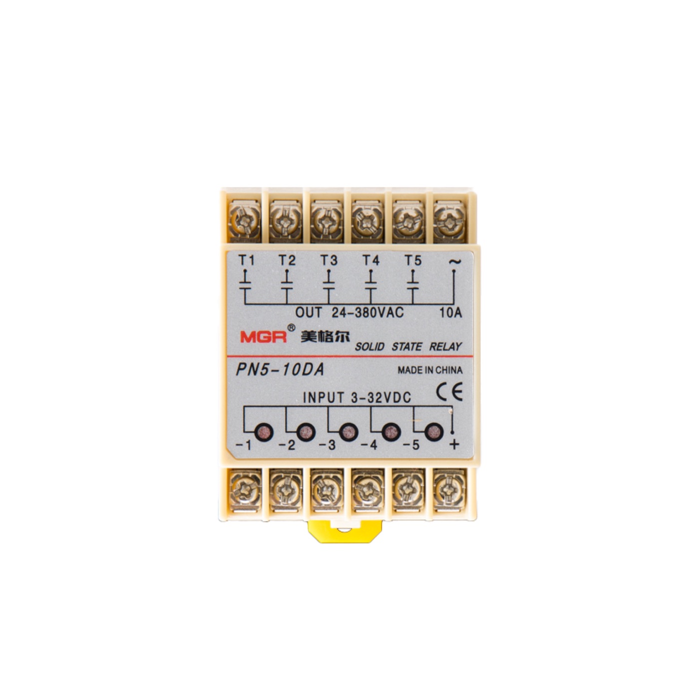
3–32 V DC control · 24–480 V AC load
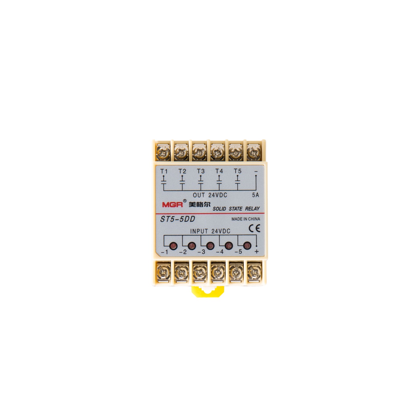
24 V DC control · 24 V DC load
Five channels.
One clear layout.
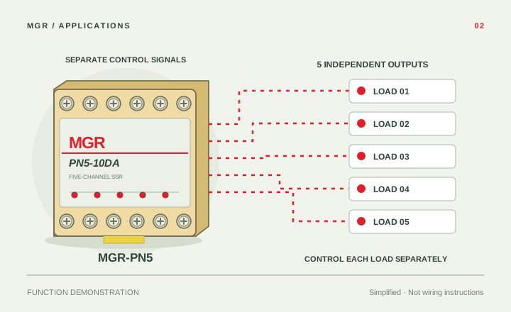
Switch five different loads with five separate control signals. Both series combine individual channel indicators, accessible screw terminals and a compact metal-base housing.
Compact multi-load control
Five switching channels in one enclosure help simplify installations with limited cabinet space.
Low-loss output
Low off-state leakage and low on-state voltage drop.
PN5 · AC switching
DC control with an RC snubber included in the AC output circuit.
ST5 · DC switching
Low-impedance MOSFET outputs help reduce output power consumption.
Match the output
to your load.
Electrical reference for PN5 and ST5, based on the product datasheets. Both series are available in 5 A and 10 A versions.
| Parameter | MGR-PN5AC OUTPUT | MGR-ST5DC OUTPUT |
|---|---|---|
| Reference model | PN5-10DA | ST5-5DD |
| Switching type | DC control → AC load | DC control → DC load |
| Control voltage | 3–32 V DC | 24 V DC |
| Rated load voltage | 24–480 V AC | 24 V DC |
| Maximum rated load current options | 5 A / 10 A | 5 A / 10 A |
| Control current | ≤10 mA | Not specified in the datasheet |
| Output design | AC switching · RC snubber | Low-impedance MOSFET |
| Load common | ~ | − |
| Independently controlled channels | 5 | 5 |
| Control common | + | + |
| Status indication | Five separate output LEDs | Five separate output LEDs |
| Enclosure / connections | Metal base · screw terminals | Metal base · screw terminals |
| Overall dimensions | 65 × 51 × 30 mm | 65 × 51 × 30 mm |
The datasheets illustrate PN5-10DA (10 A) and ST5-5DD (5 A). Both series also offer 5 A / 10 A current options. PN5 rated load voltage follows the datasheet: 24–480 V AC; the product photograph and wiring example show a 380 V AC version.
Two output types.
The same footprint.
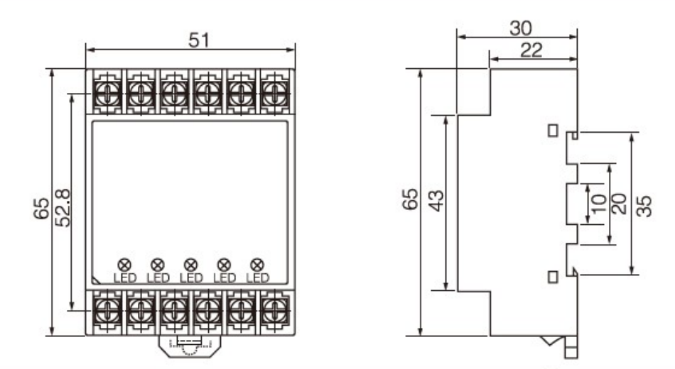
Both enclosures measure 65 × 51 × 30 mm. The original drawing below also shows the 52.8 mm terminal spacing and the 35 mm mounting profile. All dimensions are in millimetres.
Choose your connection.
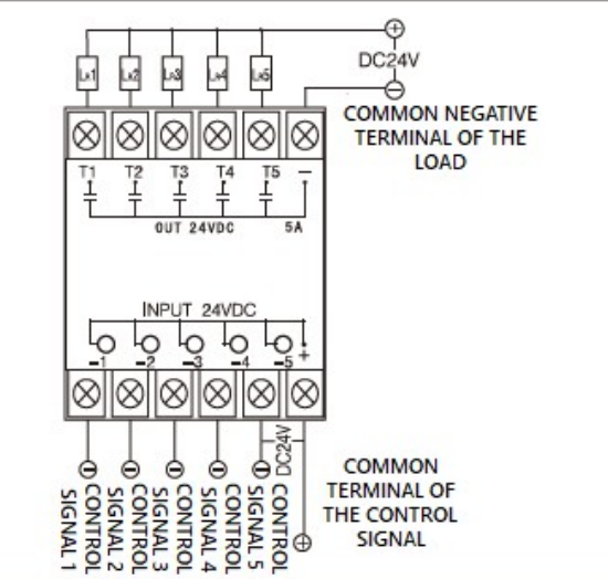
Each input controls the matching output: −1 → T1, through −5 → T5. Control inputs share a common + terminal. Select the output type to view its load connections.
3–32 V DC input
Connect the control common to +, and the five individual control signals to −1 through −5.
AC output
Connect each load between one AC supply conductor and its matching output T1 through T5. Connect the other supply conductor to the common ~ terminal.
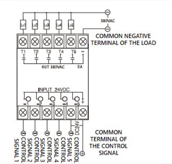
24 V DC input
Connect the control common to +, and the five individual control signals to −1 through −5.
24 V DC output
Connect the load-supply negative to the common − terminal. Connect each load between +24 V DC and its matching output T1 through T5.
More loads.
Less cabinet space.
For heating and cooling equipment, lighting systems, food-processing machinery and remote-control systems that require several independently switched loads. Match the selected AC or DC output to the connected load.
See the switching function.
Each negative control input −1 to −5 operates its matching output T1 to T5. The control inputs share a common + terminal. PN5 uses AC output; ST5 uses DC output with load polarity.