← Bridge rectifiersMGR-KBPC
SINGLE-PHASE / AC TO DC
MGR-KBPC
Series
Full-wave rectification for equipment power circuits. Choose the load current, then confirm the exact device rating and cooling arrangement.
KBPC15-10 · 15 AKBPC25-10 · 25 AKBPC35-10 · 35 AKBPC50-10 · 50 A
01 / CONNECTIONS
Follow the terminal markings.
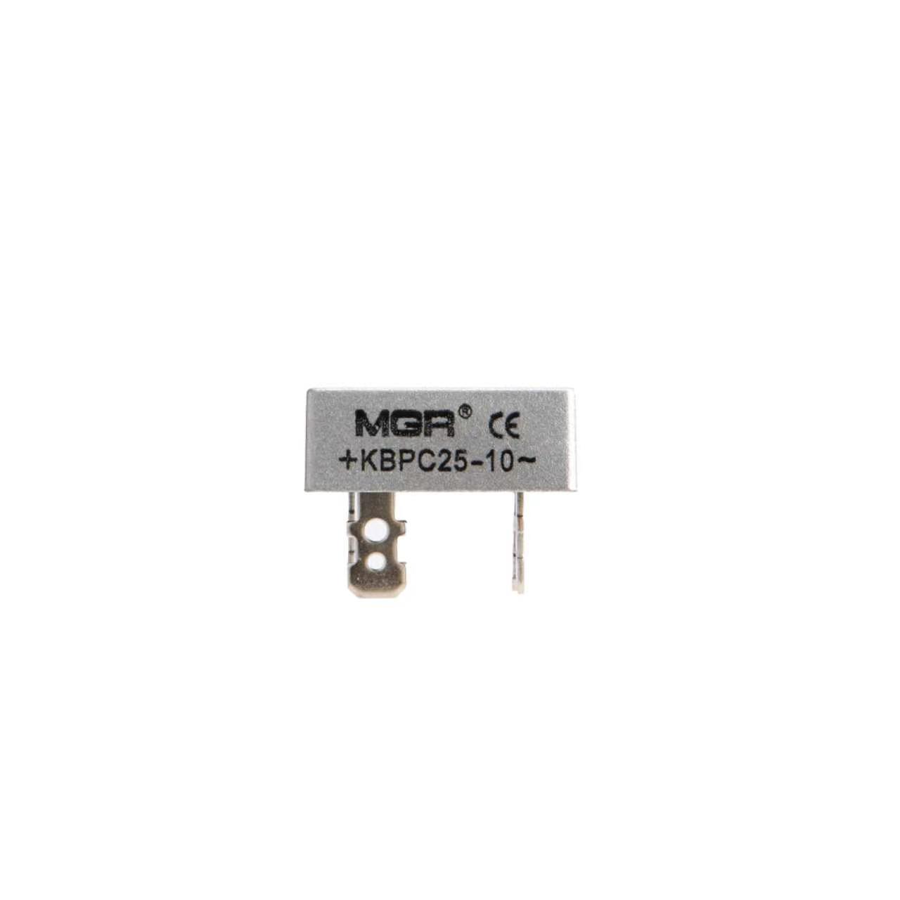
Connect the AC source to the two ~ terminals. Take the rectified output from + and −. Identify these markings on the actual device; the functional diagram does not specify the physical terminal positions.
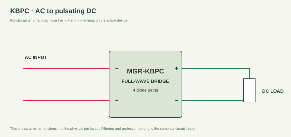
The bridge output is pulsating DC. Smoothing, regulation, protection and cooling depend on the complete circuit design.
02 / WORKING PRINCIPLE
Two half-cycles.
One output polarity.
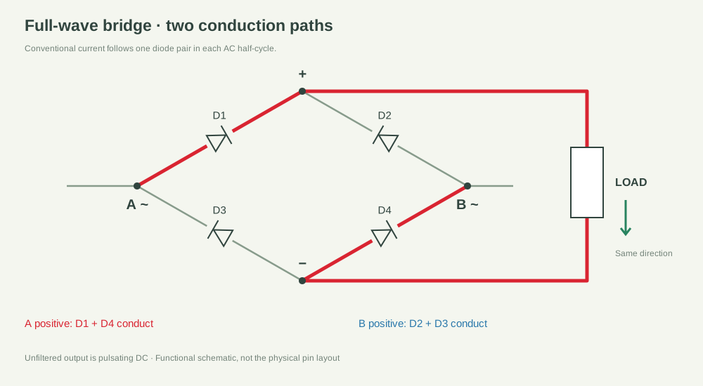
In one half-cycle, D1 and D4 conduct. In the other, D2 and D3 conduct. Both paths drive current through the load in the same direction. The animation shows conventional current; its timing is illustrative.