← All voltage regulators

PANEL MOUNT / SINGLE-PHASE / SIGNAL INPUT

MGR-DT
Series

High-current solid state voltage regulators for proportional control of industrial resistive AC loads. Select the voltage platform, current rating and enclosure form for the installation.

Ask about this series ↗
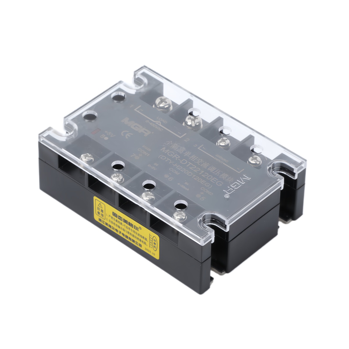
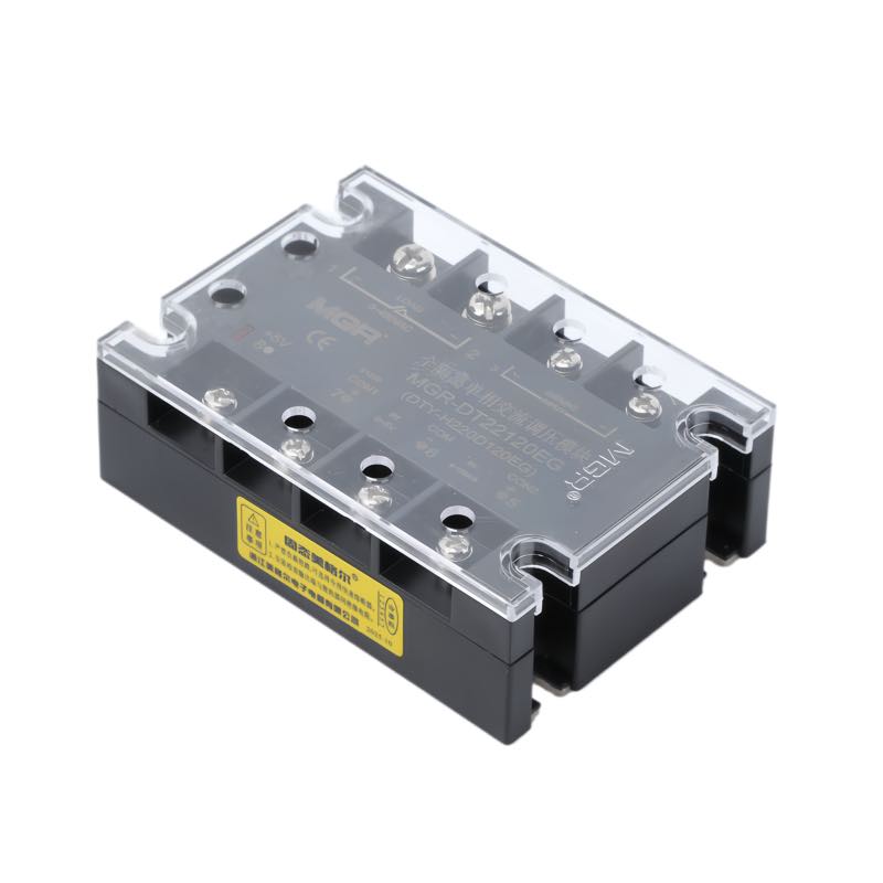
MGR-DT22120EG solid state voltage regulator
MGR-DT22120EG · 220 V platform · 120 A representative model
01 / MODEL RANGE

Three naming platforms.

The middle current number identifies the maximum rated load current. Choose the 220 V or 380 V voltage-regulation platform first; the -II suffix identifies an alternate enclosure form.

220 V AC REGULATION

MGR-DT22--EG

22 denotes the 220 V AC voltage-regulation platform. Example: MGR-DT22120EG.

380 V AC REGULATION

MGR-DT38--EG

38 denotes the 380 V AC voltage-regulation platform. Select the current code to suit the load.

ALTERNATE ENCLOSURE

MGR-DT--EG-II

-II denotes a different product appearance / enclosure form. Confirm dimensions before installation.

15 A
MGR-DT2215EG
MGR-DT3815EG
MGR-DT15EG-II
25 A
MGR-DT2225EG
MGR-DT3825EG
MGR-DT25EG-II
40 A
MGR-DT2240EG
MGR-DT3840EG
MGR-DT40EG-II
60 A
MGR-DT2260EG
MGR-DT3860EG
MGR-DT60EG-II
80 A
MGR-DT2280EG
MGR-DT3880EG
MGR-DT80EG-II
120 A
MGR-DT22120EG
MGR-DT38120EG
MGR-DT120EG-II
150 A
MGR-DT22150EG
MGR-DT38150EG
MGR-DT150EG-II
200 A
MGR-DT22200EG
MGR-DT38200EG
MGR-DT200EG-II
02 / PRODUCT VIEWS

Compare both housings,
angle by angle.

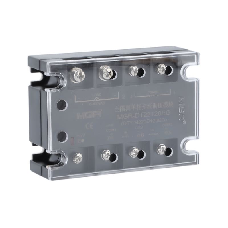
Each column pairs the same viewing angle: black standard housing above, white -II housing below.
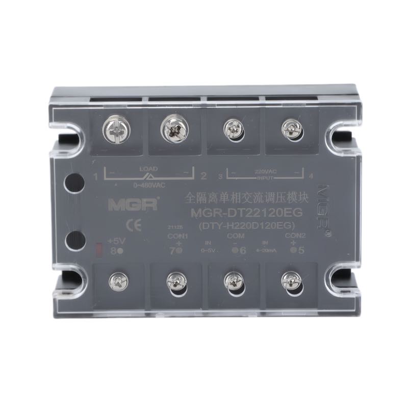
01 · Front

Standard black housing, front view
Standard · DT22 / DT38
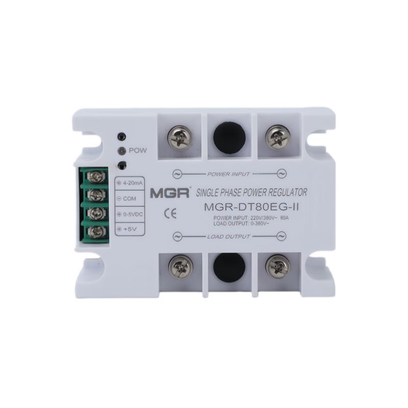
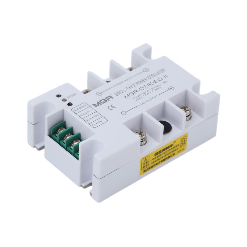
White -II housing, front view
Alternate · DT--EG-II

02 · Three-quarter A

Standard black housing, three-quarter view A
Standard · DT22 / DT38
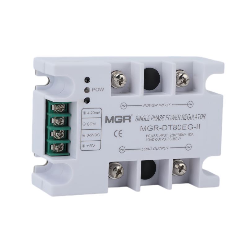
White -II housing, three-quarter view A
Alternate · DT--EG-II

03 · Three-quarter B

Standard black housing, three-quarter view B
Standard · DT22 / DT38
White -II housing, three-quarter view B
Alternate · DT--EG-II

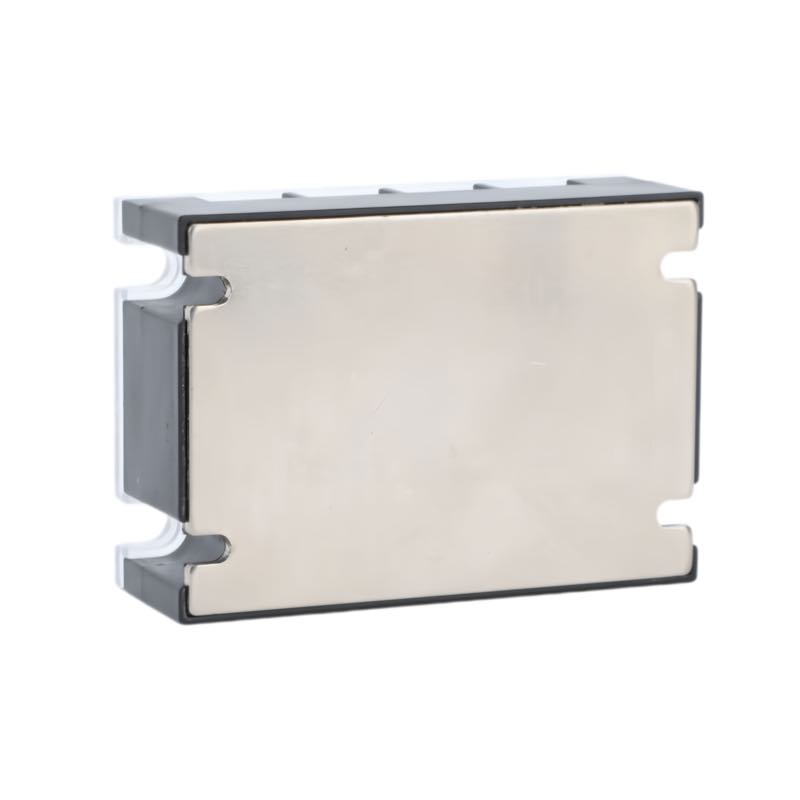
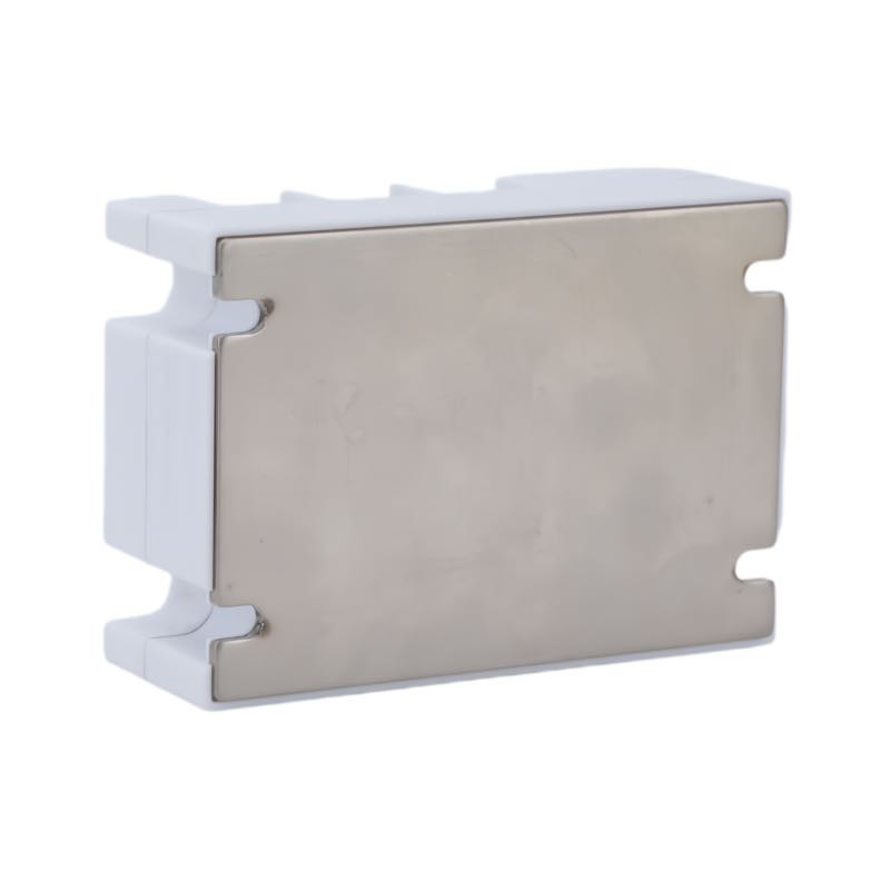
04 · Rear / mounting base

Standard black housing, rear mounting base view
Standard · DT22 / DT38
White -II housing, rear mounting base view
Alternate · DT--EG-II
03 / PARAMETERS

Fully isolated.
Precisely controlled.

The MGR-DT is an all-isolated single-phase AC voltage regulator module. Its control and power sections are electrically isolated, with synchronized phase detection and thyristor phase-angle control regulating the AC output.

01 / ISOLATION

Full electrical isolation

The power section is isolated from the low-level control circuit, as described in the MGR-DT catalogue.

02 / CONTROL

Multiple signal versions

Catalogue-listed options include 0–5 VDC and 4–20 mA (EG), 0–10 VDC (F), and 1–5 VDC (H). Available signal depends on the exact ordered variant.

03 / REGULATION

Phase-angle AC regulation

A synchronous transformer and phase-detection circuit provide thyristor trigger timing to regulate the AC output according to the control signal.

Product typeAll-isolated, single-phase AC voltage regulator (SSVR)
Voltage platformsDT22: 220 VAC nominal · DT38: 380 VAC nominal
Allowable input rangeDT22 / 220 VAC version: 165–240 VAC · DT38 / 380 VAC version: 285–420 VAC
Control signalsVariant-dependent: 0–5 VDC / 4–20 mA (EG), 0–10 VDC (F), or 1–5 VDC (H)
Isolation voltageMore than 2000 VAC between the power section, control section and module base
Current codes15 / 25 / 40 / 60 / 80 / 120 / 150 / 200 A maximum-rated models
II suffixAlternate external housing / appearance
Thermal integrationConfirm heat-sink and installation requirement against selected current and duty cycle
04 / DIMENSIONS

Two housing drawings.

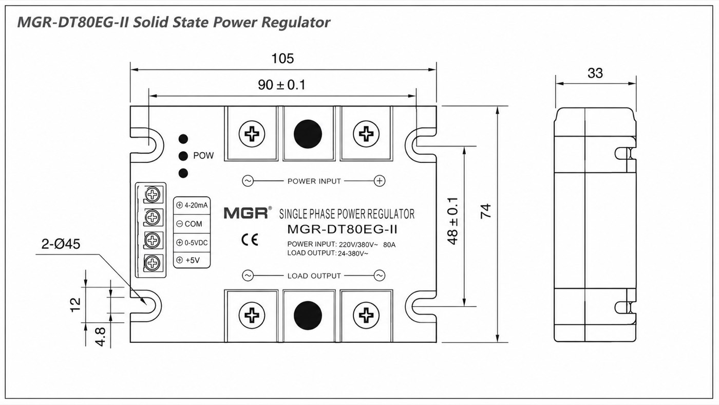
Both source drawings are included so the terminal layouts are clear before panel design. All dimensions are in millimetres.
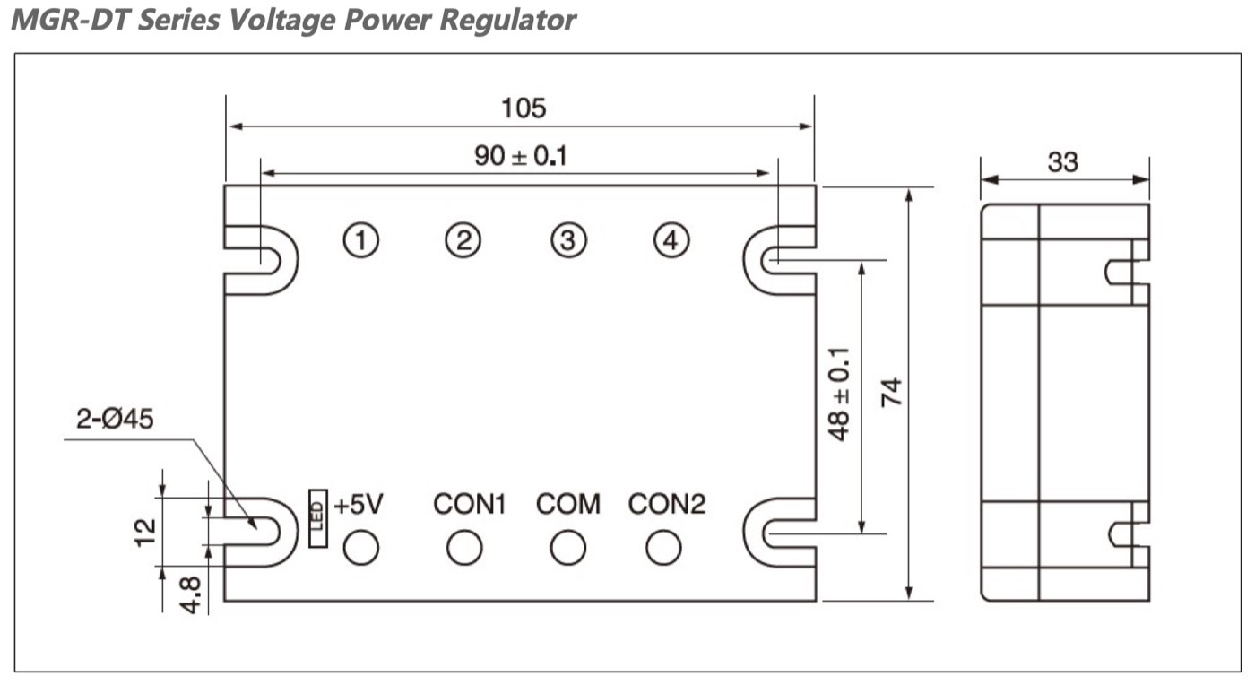
MGR-DT22 and DT38 housing dimensions: 105 by 74 by 33 millimetres
DT22 / DT38 platform · 105 × 74 × 33 mm · select to view full size
MGR-DT80EG-II housing dimensions: 105 by 74 by 33 millimetres
MGR-DT--EG-II platform · 105 × 74 × 33 mm · select to view full size
05 / WIRING & CONTROL

Connection diagrams
and control behavior.

Reference circuits from the MGR-DT technical catalogue, plus a direct terminal-by-terminal connection guide for the alternate -II housing.
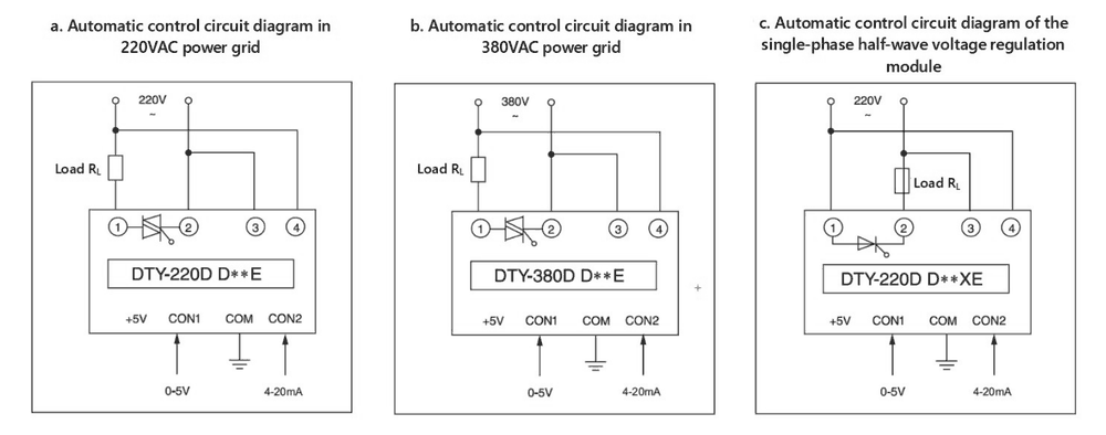
MGR-DT automatic control circuits for 220 VAC, 380 VAC, and half-wave versions
Standard DT automatic control wiring · 220 VAC and 380 VAC versions, plus a separate half-wave circuit for X-suffix models. Select to enlarge.
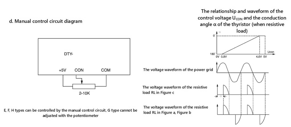
MGR-DT manual potentiometer connection and 0 to 5 volt control-angle and waveform diagrams
Manual potentiometer circuit and 0–5 VDC control-angle / waveform reference. Catalogue notes manual potentiometer control for E, F and H types; G (4–20 mA) is not potentiometer-adjustable.

ALTERNATE -II HOUSING

How to connect

Follow the actual front-terminal arrangement: AC supply to the upper pair, single-phase AC load to the lower pair, and the control signal to the matching side terminal.
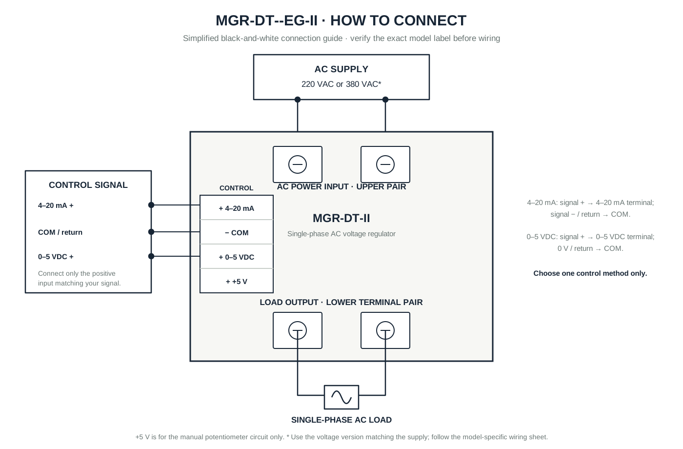
  • 4–20 mA: signal + to 4–20 mA; signal − / return to COM.
  • 0–5 VDC: signal + to 0–5 VDC; 0 V / return to COM.
  • Use only one control input. +5 V is for the manual potentiometer circuit only.
MGR-DT-II wiring diagram showing upper AC input, lower AC load output and selected control signal connections
06 / HOW TO SPECIFY

Start with voltage, then current.

Use the model pattern below to communicate the primary requirements clearly.

220 V PLATFORMMGR-DT22 + current + EG
380 V PLATFORMMGR-DT38 + current + EG
ALTERNATE HOUSINGMGR-DT + current + EG-II

SELECT YOUR MGR-DT REGULATOR

Tell us the load, voltage platform and required current.

sales@mgrssr.com ↗