THREE-PHASE / FORWARD & REVERSE / PANEL MOUNT
MGR-3 MSeries
Two directions.
One solid state controller.
DC-controlled switching for three-phase AC reversible motors, with built-in forward/reverse interlock and two-colour output indication.
Compare models ↗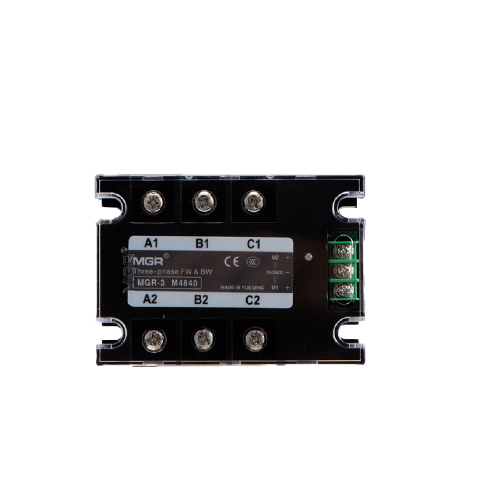
01 / OVERVIEW
Built for changing
direction.
The MGR-3 M series controls the rotation direction of a three-phase AC motor using DC control signals. A panel-mount enclosure brings the power and control connections together in a compact format.
Forward / reverse interlock
Built-in interlock protection for direction control.
Two-colour indication
Red and green LEDs indicate output status.
RC snubber circuit
Standard output RC snubber included.
Low-loss switching
Low off-state leakage, low on-state voltage drop and low input current.
02 / MODELS & SPECIFICATIONS
Select your controller.
Choose from 25 A, 40 A, 60 A and 80 A ratings. Ratings above 40 A require a custom order. Load-voltage ratings above 480 V AC are also custom-made, up to a maximum of 750 V AC.
MGR-3 M4825
Standard option · 480 V AC
MGR-3 M4840
Standard option · 480 V AC
Custom order
Confirm voltage and model code
Custom order
Confirm voltage and model code
Standard model examples: 3 = Three-phase · M = Forward / reverse · 48 = 480 V AC · 25 / 40 = Rated current in amperes. Custom model codes are confirmed with the order.
03 / PRODUCT VIEWS
A closer look.
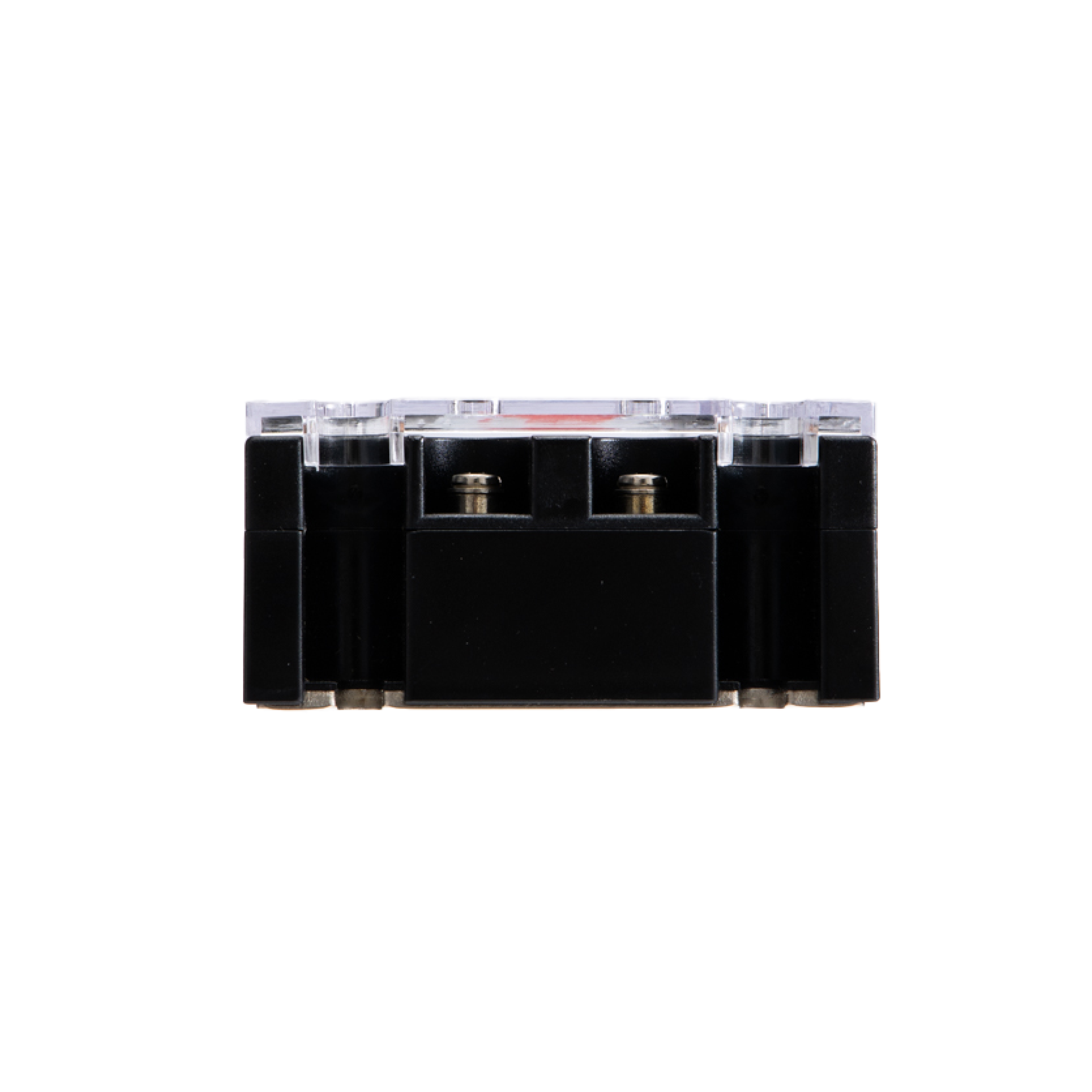
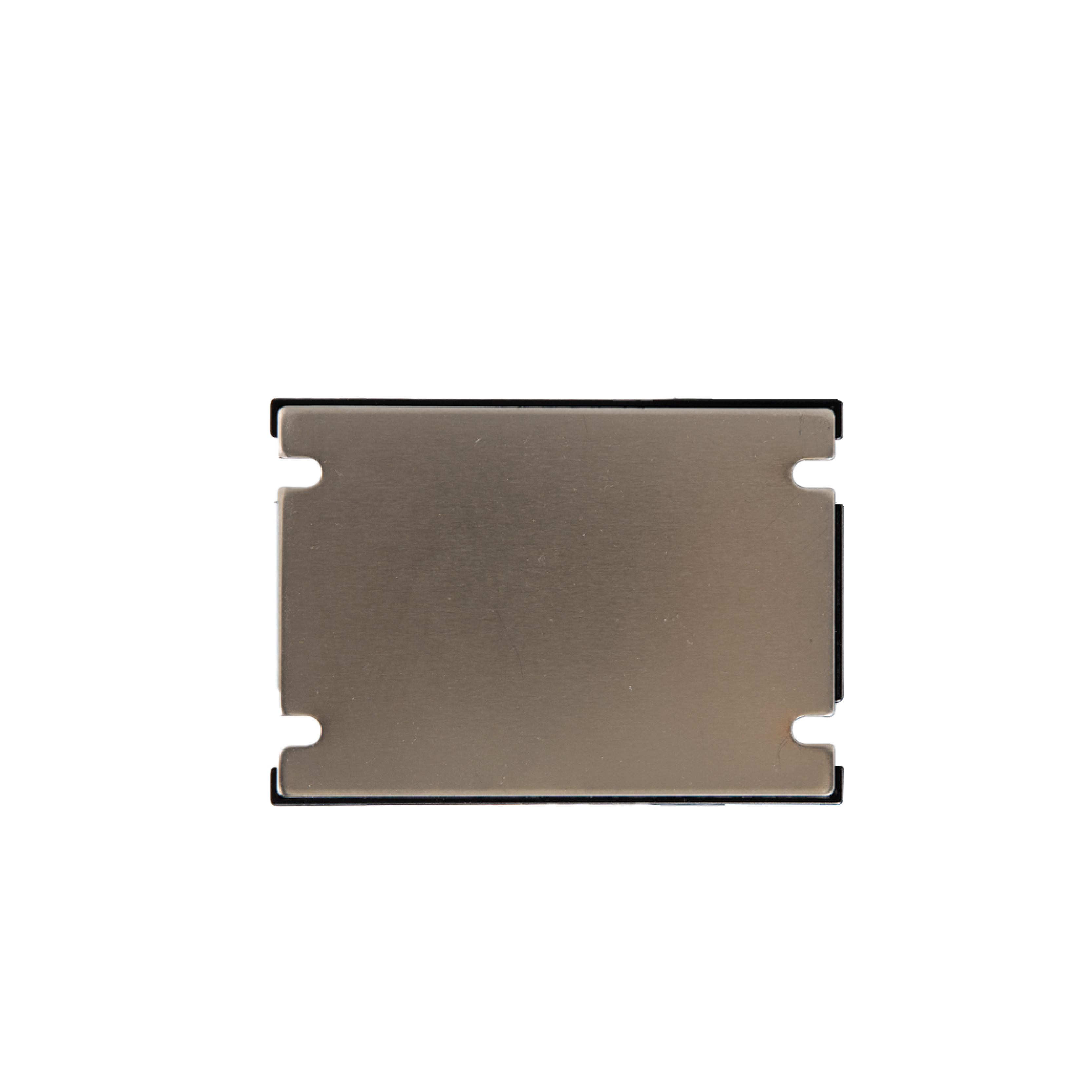
Front connections, side profile and metal mounting base. Product photographs are for housing and terminal reference; check the label on the selected model.
04 / DIMENSIONS & DIAGRAM
Compact footprint.
Clear connections.
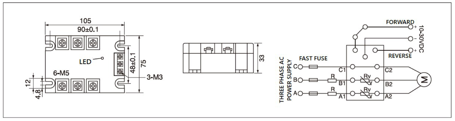
Standard housing dimensions: 105 × 75 × 33 mm. Confirm the dimensions and supplied drawing for custom current or voltage versions. Mounting centres: 90 ± 0.1 × 48 ± 0.1 mm. The drawing identifies six M5 power terminals and three M3 control terminals.
05 / CONNECTIONS
Power and control,
clearly separated.
Use the original diagram above as the connection reference. Terminal names below follow that diagram; do not identify terminals by position alone.
Three-phase AC
The source diagram shows fast fuses in the three supply conductors and additional suppression components. Coordinate external protection with the selected controller and motor.
DC direction inputs
Apply one direction command at a time. Confirm the required changeover delay for the motor and load; no reversal timing value is specified in the supplied datasheets.
06 / INSTALLATION & SELECTION
Plan for the motor,
not just the module.
Allow 5–7 times the actual motor current
Choose the controller rated current at 5–7 times the actual motor current. Share motor power, actual current, starting current and reversing frequency so we can confirm the rating, cooling and changeover sequence. Ratings above 40 A or 480 V AC require customization; the maximum custom load-voltage rating is 750 V AC.
Provide adequate cooling
The M4825 datasheet calls for a heat sink at 10 A load current, and forced-air or water cooling at 40 A and above. Confirm the thermal arrangement for the actual operating conditions.
Coordinate surge protection
The datasheet requires an external varistor for inductive loads. Confirm its rating and placement, fast-fuse coordination and motor overload protection before installation.
Technical reference: supplied MGR-3-M4825 product datasheet and MGR-3M series parameter/dimensional sheets, with current options, custom-order limits and the 5–7× current-selection guideline confirmed by MGR. The series sheets do not specify numeric leakage current, voltage drop or reversal delay; these values are not assumed here.
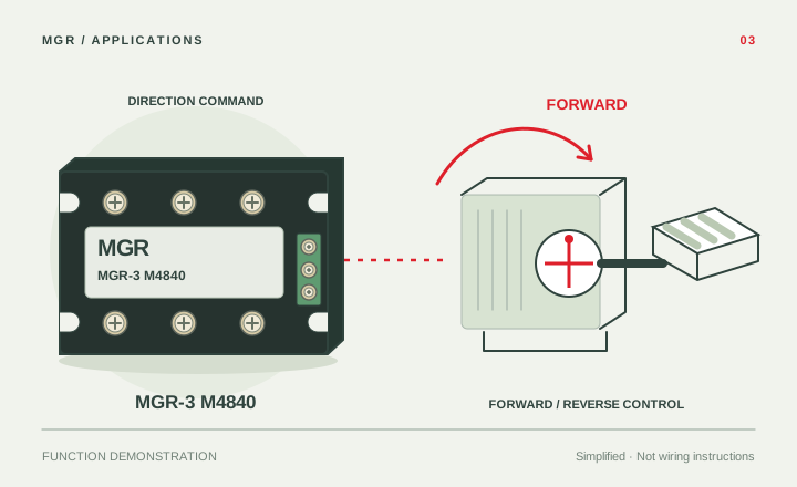
See the switching function.
One direction command at a time: forward, stop, then reverse. The built-in interlock prevents conflicting direction commands. Confirm the required changeover delay for the motor and load; the animation timing is illustrative.