DC control · AC load
3–32 V DC input · 24–480 V AC output
MGR-1 D4810-FMAX RATED LOAD CURRENT10 A
MGR-1 D4825-FMAX RATED LOAD CURRENT25 A
MGR-1 D4840-FMAX RATED LOAD CURRENT40 A

SINGLE-PHASE / REPLACEABLE FUSE
Solid state switching with a built-in, replaceable fuse. Three control and load combinations, one shared enclosure, and straightforward maintenance.
Ask about this series ↗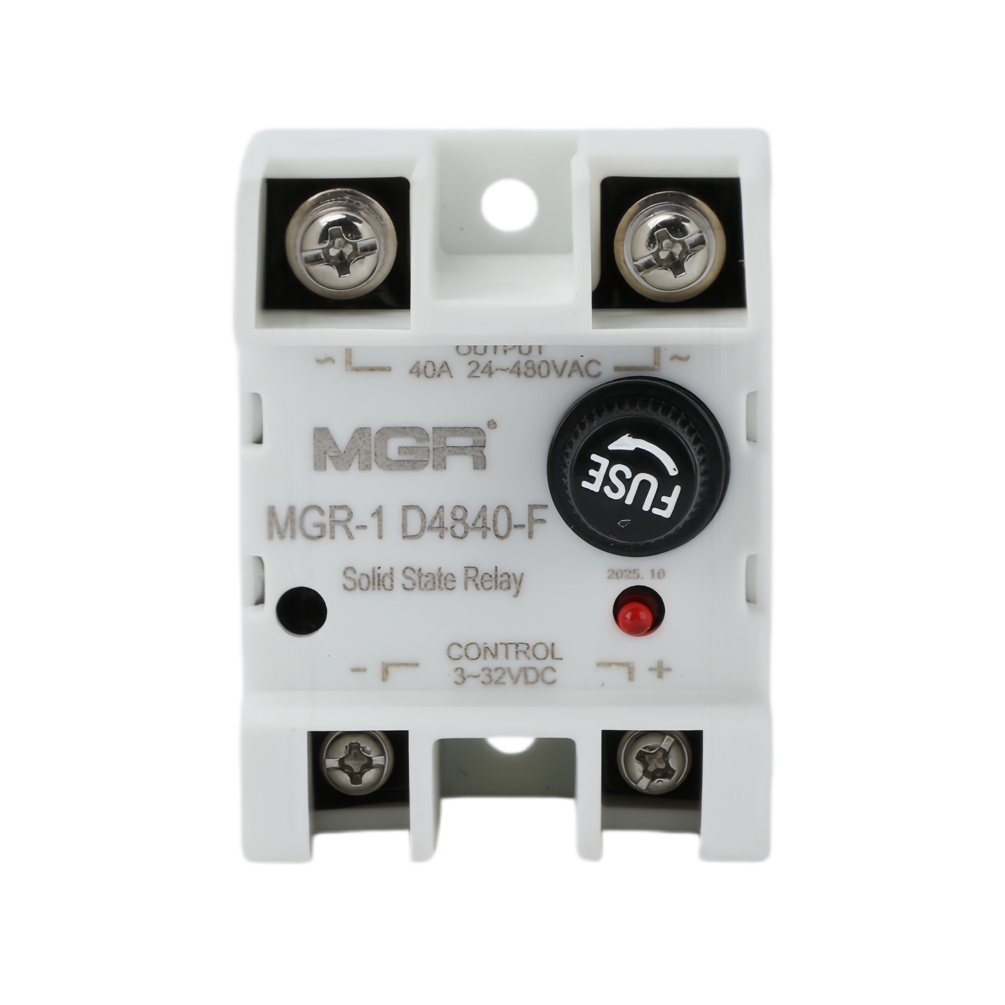
Choose the control signal and load type first, then select the maximum rated load current. All three types share the same enclosure; the model designation and electrical function differ.
3–32 V DC input · 24–480 V AC output
70–280 V AC input · 24–480 V AC output
3–32 V DC input · 5–220 V DC output
The MGR-1 D4840-F shown here represents the shared enclosure used by all three F-series types.
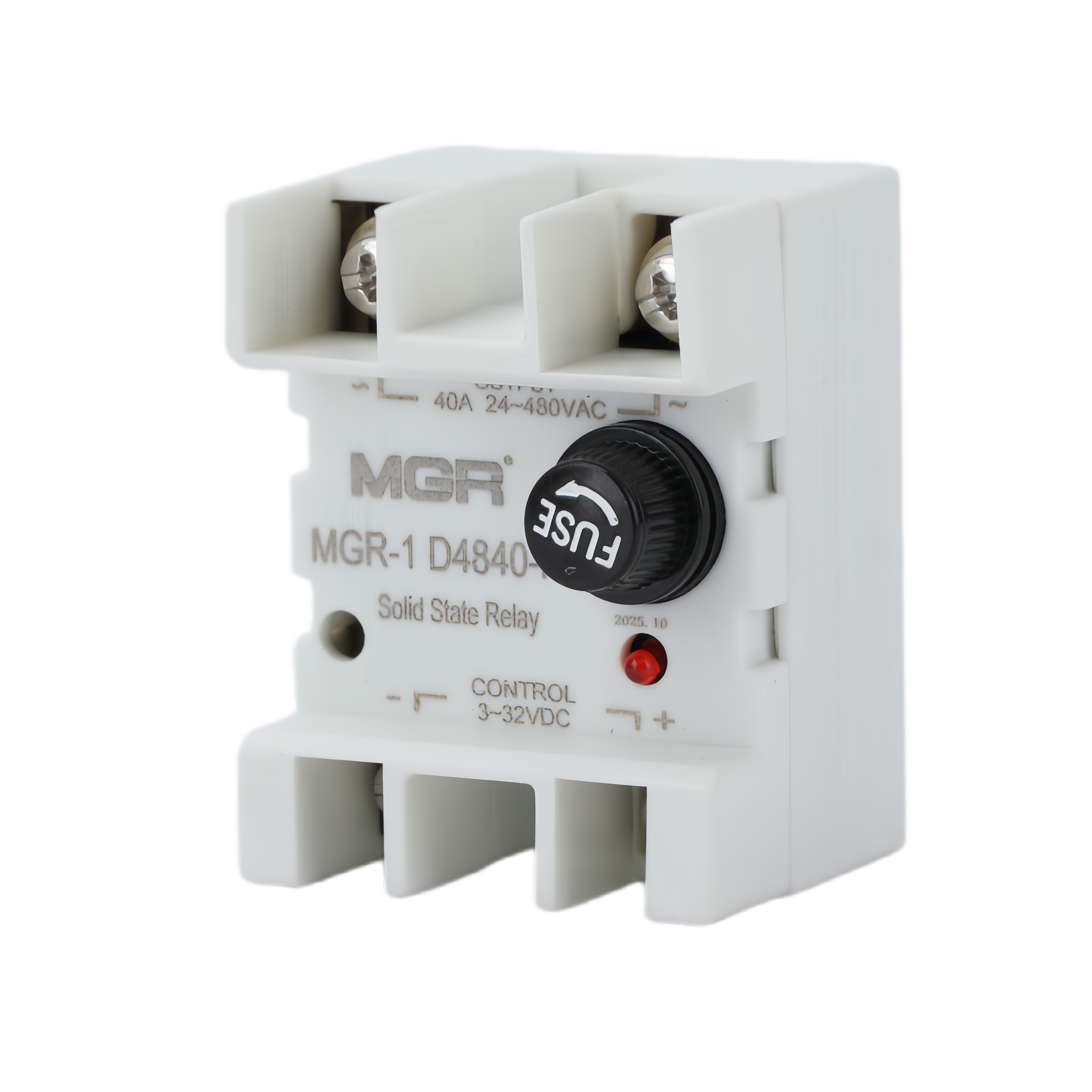
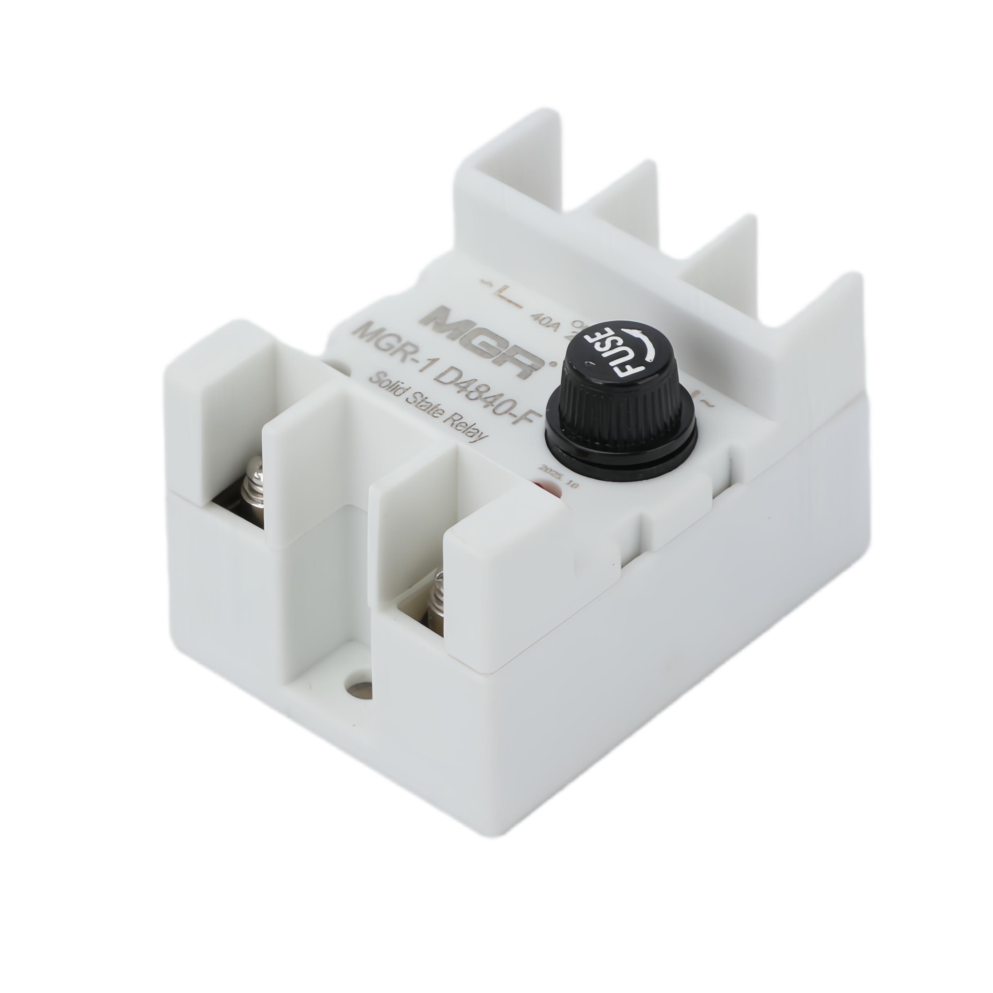
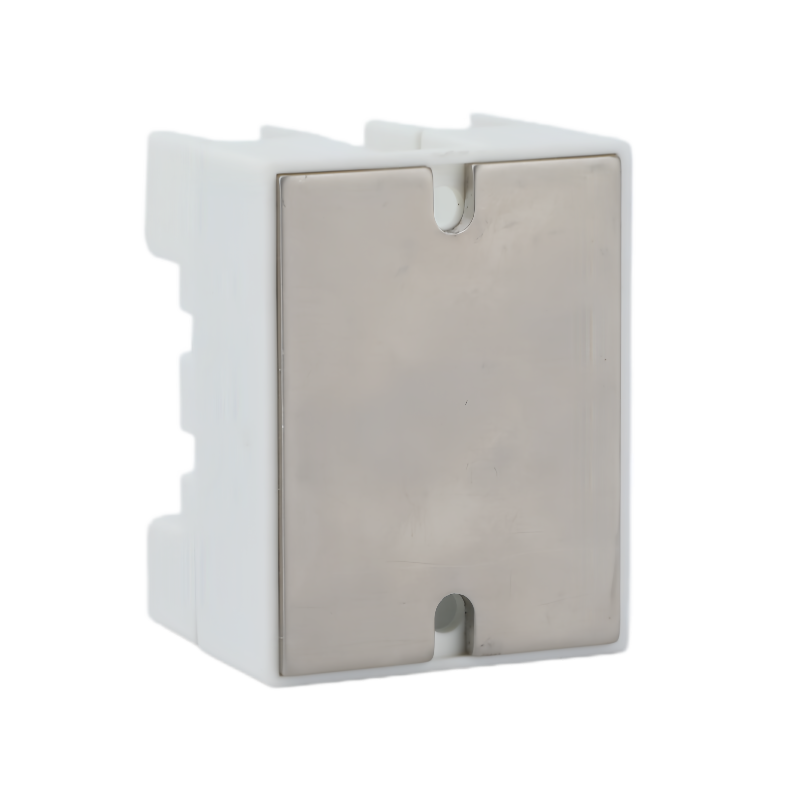
Electrical ratings follow the corresponding standard MGR-1 model. The fused range is available in 10 A, 25 A and 40 A maximum rated load-current options.
| Parameter | D48-F · DC–AC | A48-F · AC–AC | DD220D-F · DC–DC |
|---|---|---|---|
| Control voltage | 3–32 V DC | 70–280 V AC | 3–32 V DC |
| Load voltage | 24–480 V AC | 24–480 V AC | 5–220 V DC |
| Control current | ≤10 mA | ≤10 mA | ≤40 mA |
| Maximum rated load current | 10 / 25 / 40 A | 10 / 25 / 40 A | 10 / 25 / 40 A |
| Fuse | Built-in, replaceable fuse | ||
| Indication | Output-status LED | ||
| Installation | Panel / chassis mount with suitable heat sink | ||
| Enclosure dimensions | 60 × 46 × 37 mm | ||
The fused enclosure measures 60 × 46 × 37 mm. Allow access to the front fuse holder when planning the installation.
Enclosure dimensions exclude the external heat sink. Contact MGR for the mounting-hole drawing before drilling your panel.
The accessible fuse holder supports replacement without changing the complete relay when the fuse has operated and the relay remains serviceable. Commonly available fuse formats help simplify sourcing of suitable replacements.
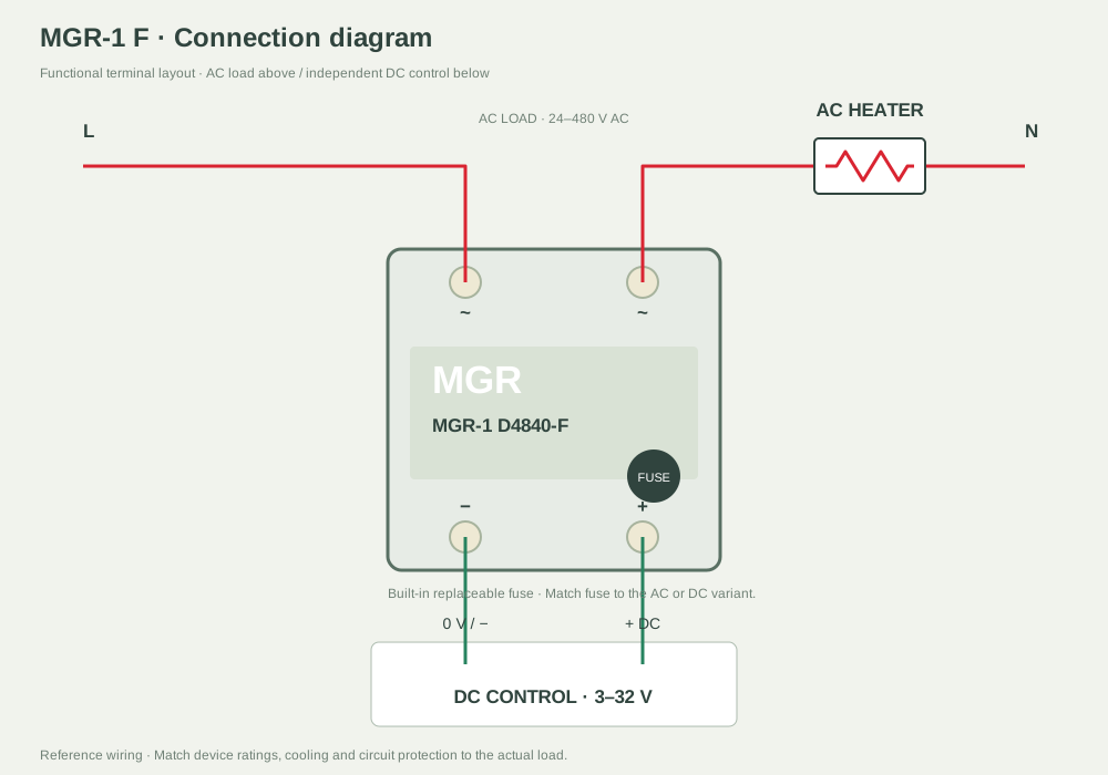
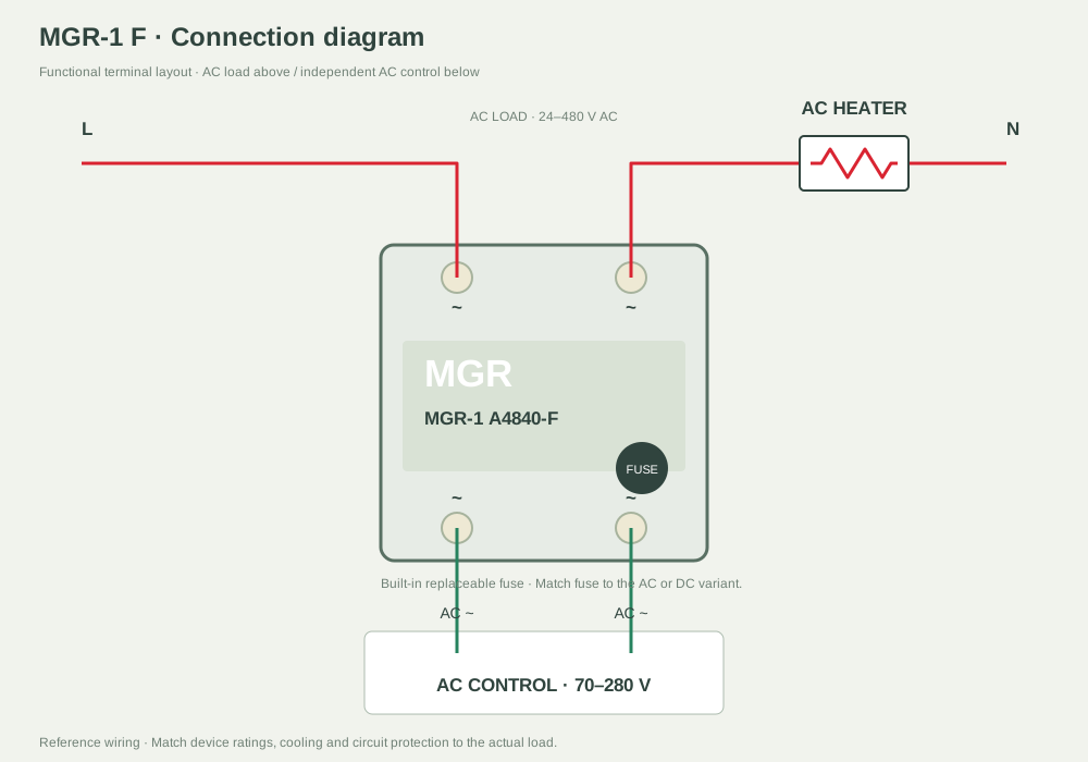
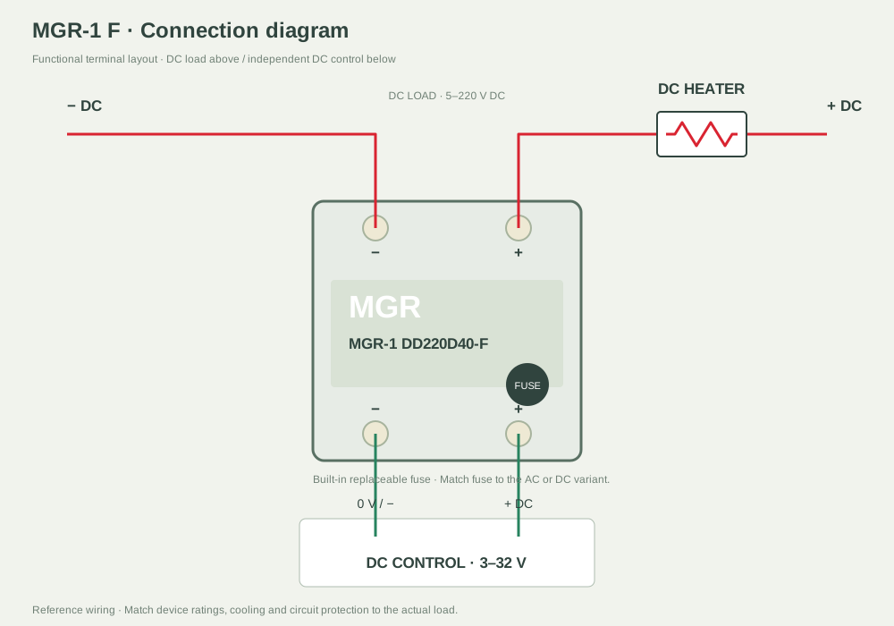
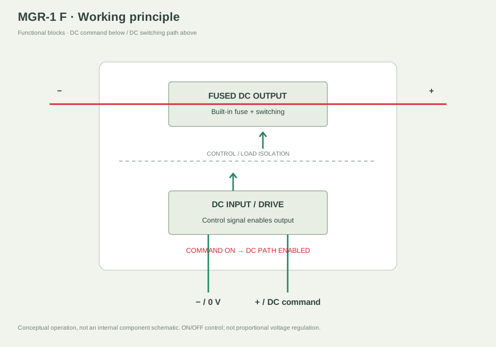
Select the matching electrical variant. Load terminals are above and control terminals below. Diagrams show terminal functions; confirm the actual markings. The fuse is built in, and its replacement rating must suit the model and AC or DC circuit.
3–32 V DC control · 24–480 V AC load
70–280 V AC control · 24–480 V AC load
3–32 V DC control · 5–220 V DC load
Select the matching electrical variant. Load terminals are above and control terminals below. Diagrams show terminal functions; confirm the actual markings. The fuse is built in, and its replacement rating must suit the model and AC or DC circuit.
3–32 V DC control · 24–480 V AC load
70–280 V AC control · 24–480 V AC load
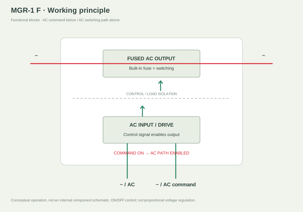
3–32 V DC control · 5–220 V DC load
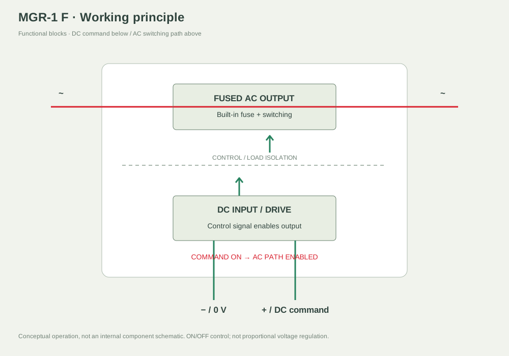
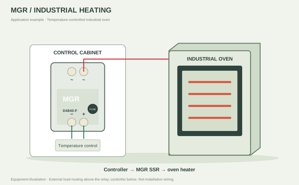
Representative D48-F application: a DC temperature controller switches an AC oven heater. Keep the front fuse holder accessible. Disconnect all supplies and resolve any fault before replacing the specified fuse.
SELECT YOUR FUSED SSR