
PANEL MOUNT / SINGLE-PHASE / DC–AC
MGR-1 D48
Series
DC-control, AC-output solid state relays for industrial switching. Choose the rated current that fits your load and thermal design.
Ask about this series ↗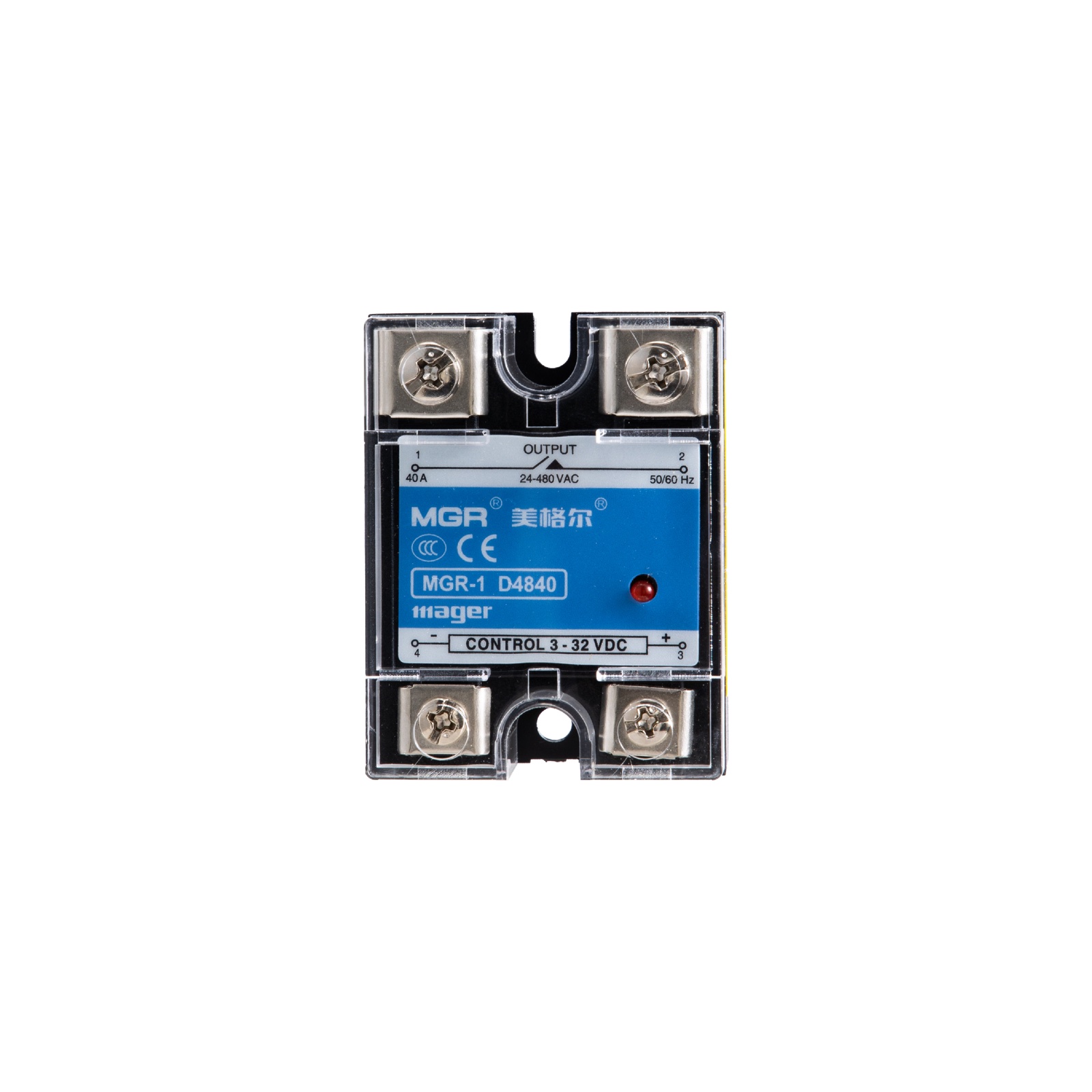
Eight current options.
Each number below is the model's maximum rated load-current value, not the current recommended for every installation. Continuous usable current depends on the heat sink, ambient temperature and mounting conditions. Confirm the exact datasheet and thermal design before use.
See every side.
Original photographs of MGR-1 D4840, showing the cover, terminals and metal mounting base.
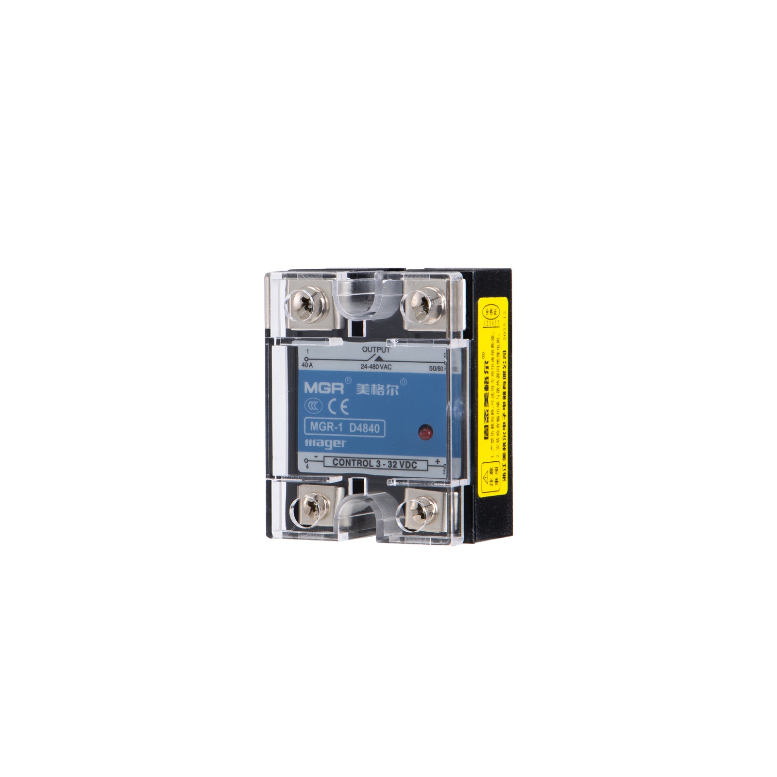
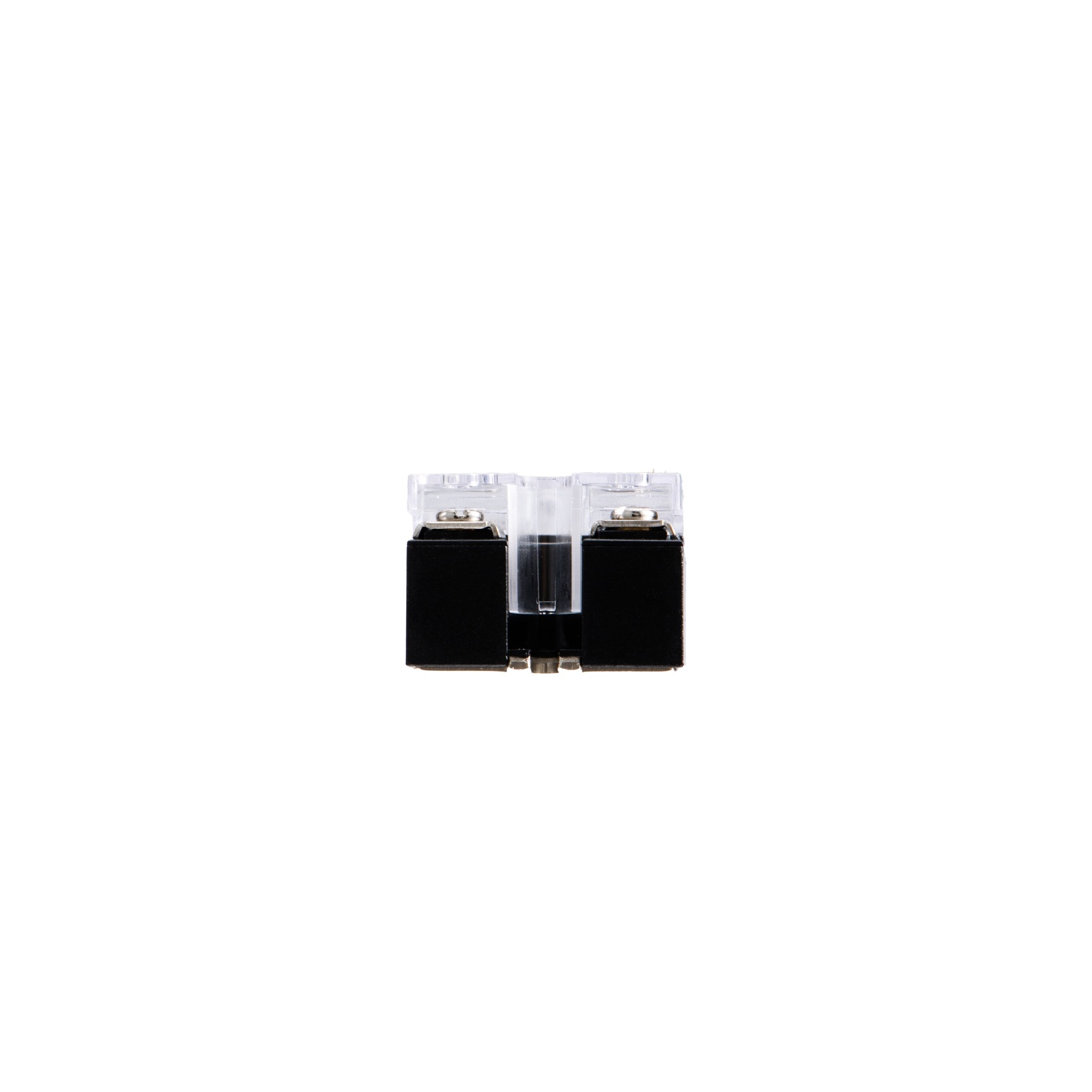
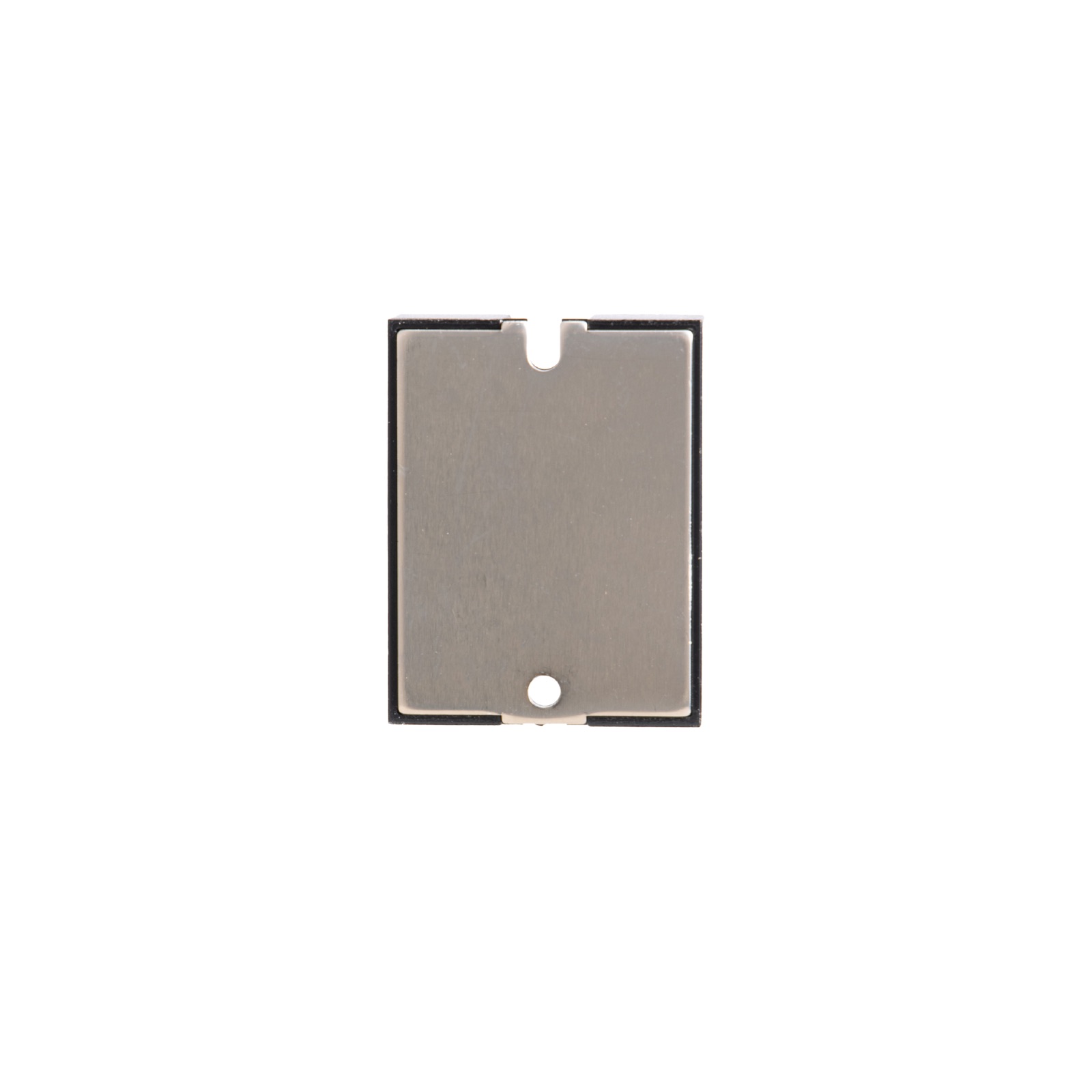
Electrical reference.
Documented values for MGR-1 D4840 (40 A). Do not apply these automatically to every current option; confirm the exact datasheet before design-in.
Measured over time.
Ten recorded test runs across five D48 models and several heat-sink setups, using heating elements as the load. Each line is labeled by the applied test current, not the relay's rated current. Temperatures are in °C; all five charts use the same 30–100 °C scale.
Ambient temperature is set to 25 °C as a common reference for this presentation. The source log did not record ambient temperature for each run, so the plotted values remain the original measured temperatures—not a calculated rise above ambient.
Recorded data (°C)
Readings above 80 °C are highlighted. The sensor position was not recorded. Blank cells mean the test log has no reading at that time.
Recommended cooling.
Heat-sink recommendations by rated current for the MGR-1 D48 series. Confirm the final thermal setup against load, duty cycle and ambient temperature.
NEED A MODEL-SPECIFIC DATASHEET?