← All products

PANEL MOUNT / SINGLE-PHASE / AC–AC

MGR-1 A48
Series

AC-control, AC-output solid state relays for industrial switching, with zero-cross or random-conduction options for compatible loads.

Ask about this series ↗
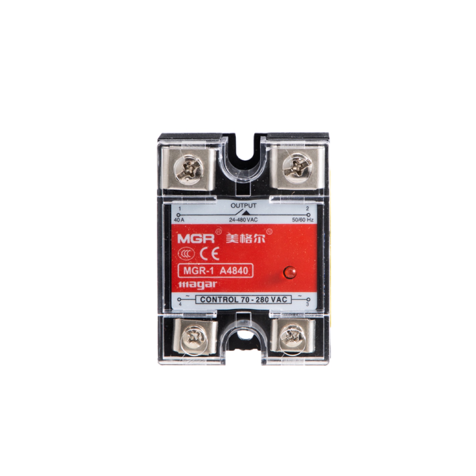
MGR-1 A4840 straight front view
MGR-1 A4840 · front view
01 / MODEL RANGE

Eight current options.

Each number below is the model's maximum rated load-current value, not the current recommended for every installation. Continuous usable current depends on the heat sink, ambient temperature and mounting conditions.

MGR-1 A4810MAX RATED LOAD CURRENT10 A
MGR-1 A4825MAX RATED LOAD CURRENT25 A
MGR-1 A4840MAX RATED LOAD CURRENT40 A
MGR-1 A4860MAX RATED LOAD CURRENT60 A
MGR-1 A4880MAX RATED LOAD CURRENT80 A
MGR-1 A48100MAX RATED LOAD CURRENT100 A
MGR-1 A48120MAX RATED LOAD CURRENT120 A
MGR-1 A48150MAX RATED LOAD CURRENT150 A
02 / PRODUCT VIEWS

See every side.

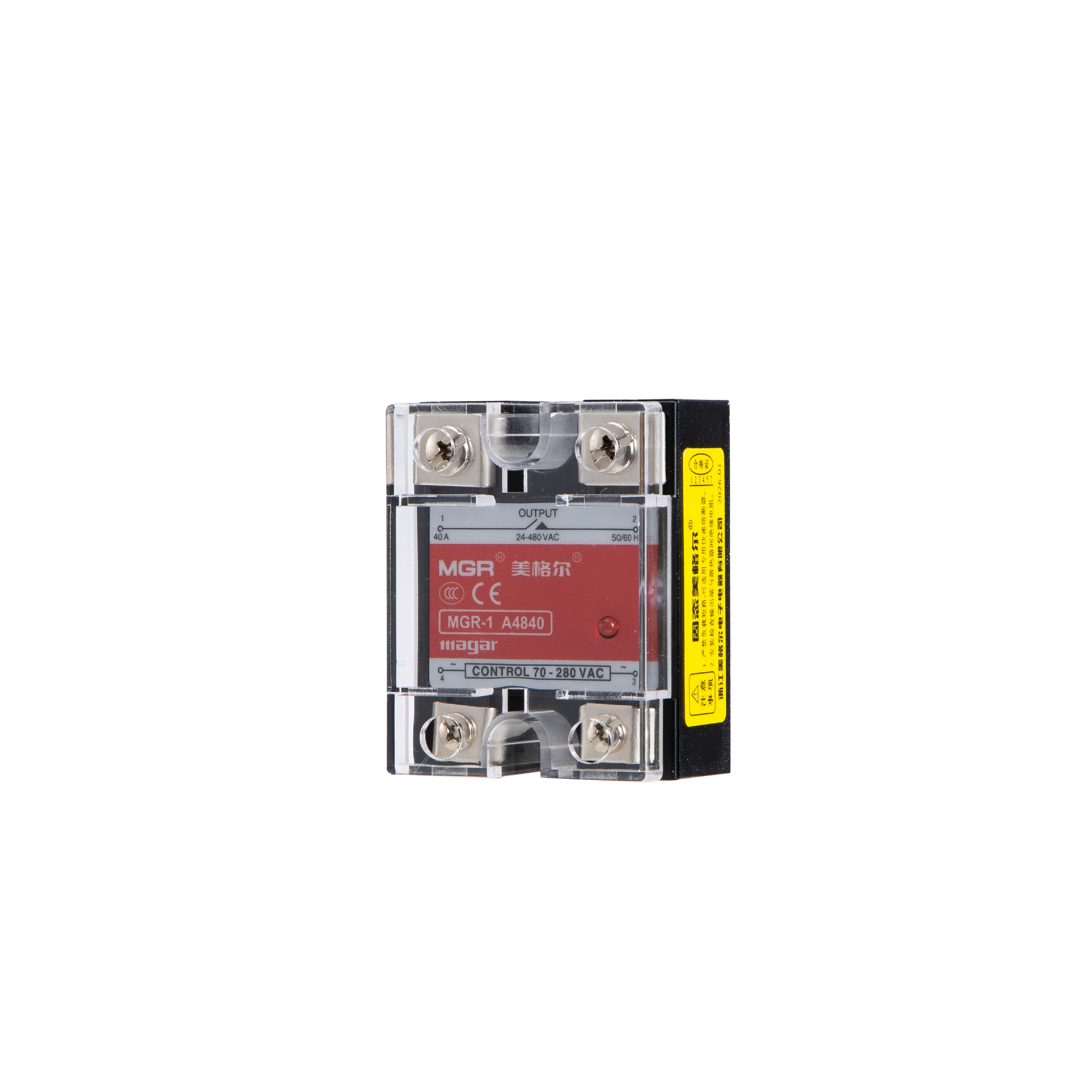
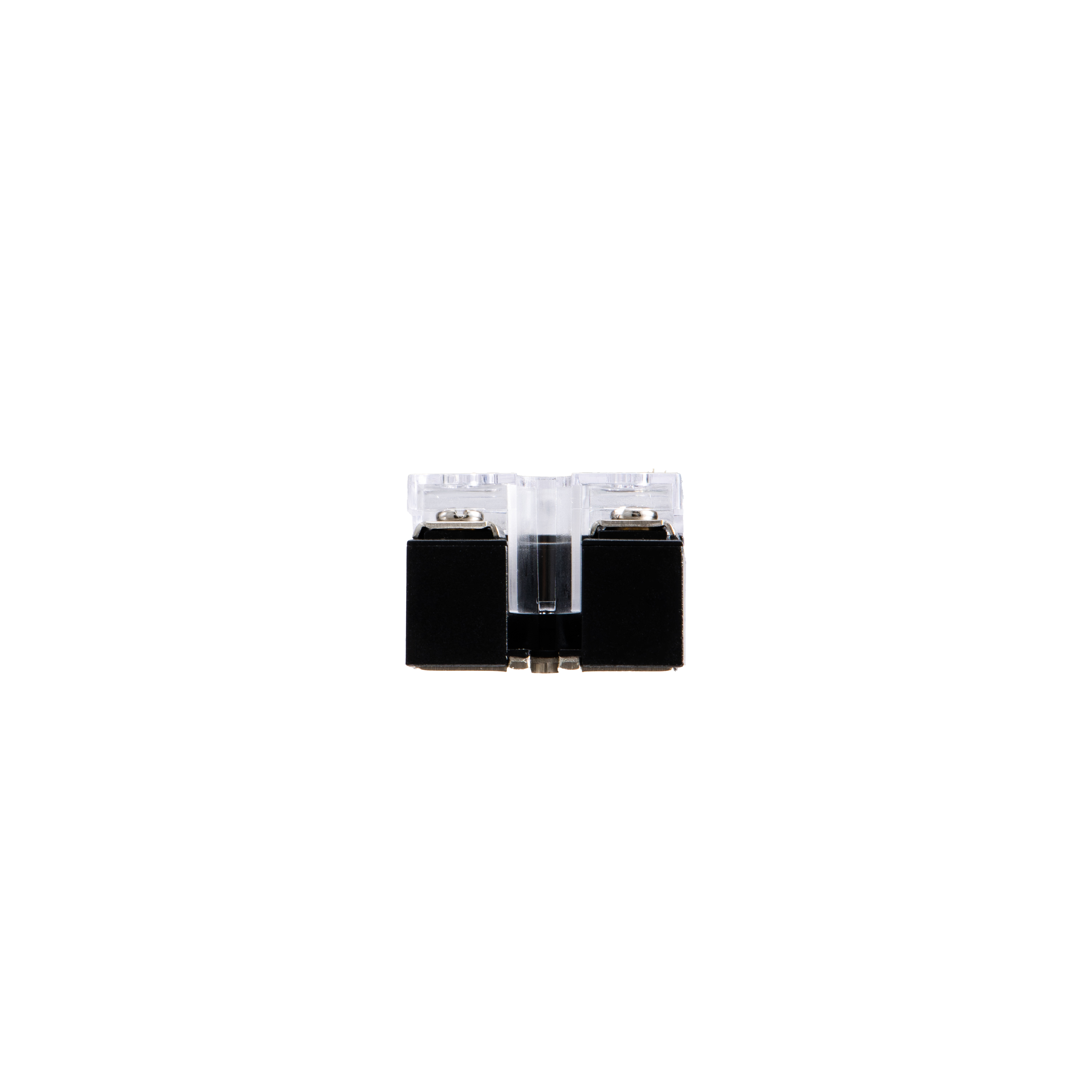
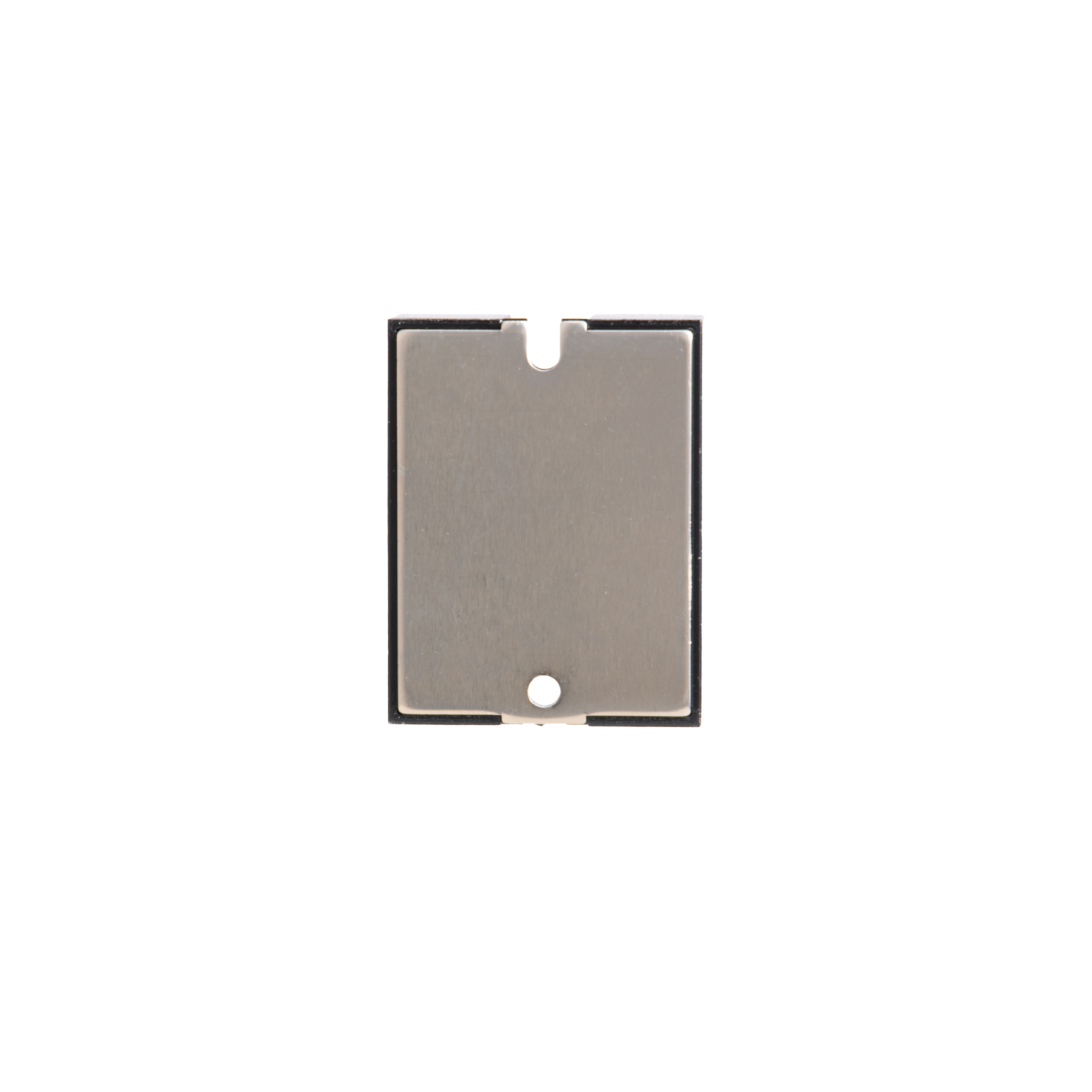
White-background product views of the MGR-1 A4840 from the official MGR product archive.
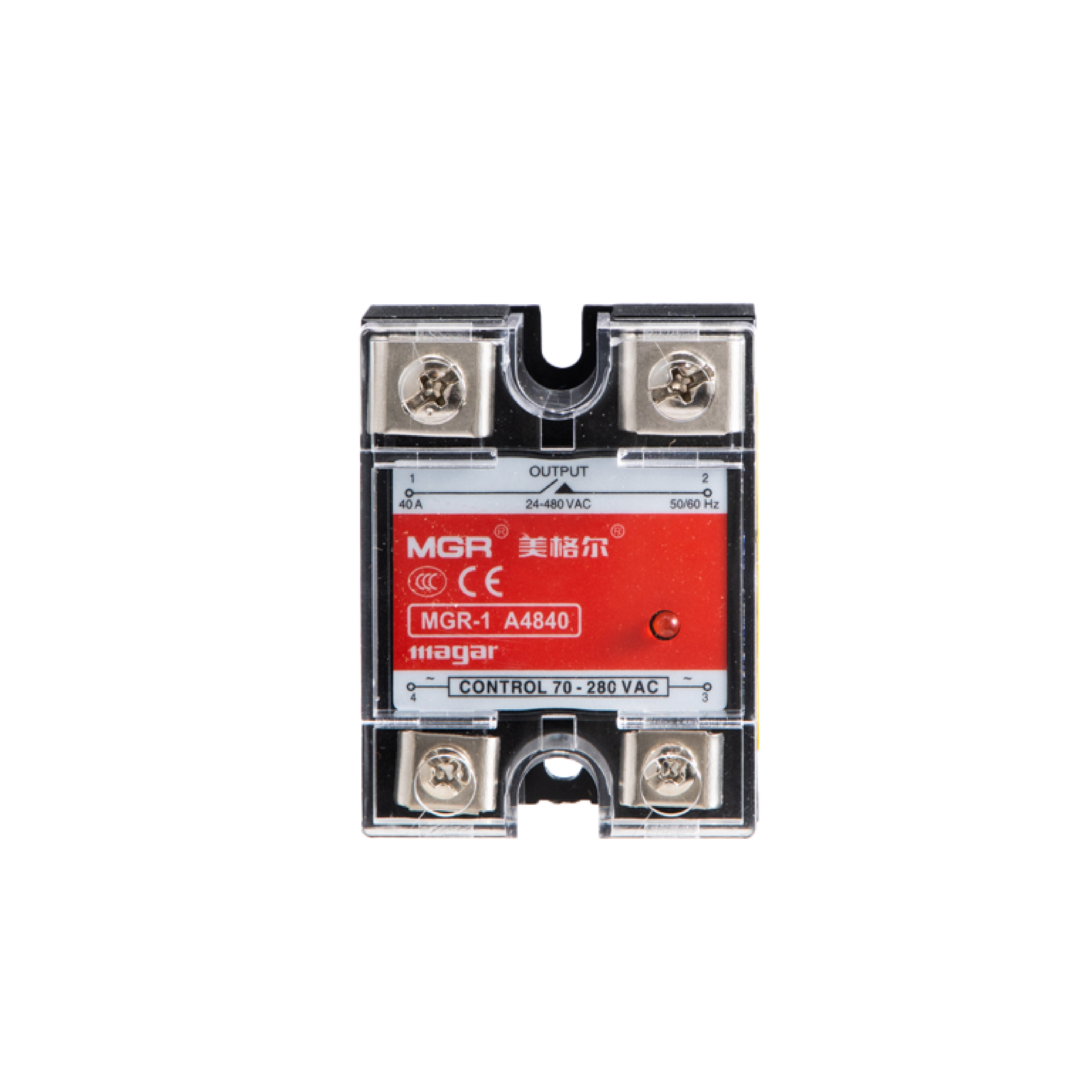
MGR-1 A4840 front view on white background
01 · Front
MGR-1 A4840 three-quarter view on white background
02 · Three-quarter
MGR-1 A4840 terminal-side view on white background
03 · Terminal side
MGR-1 A4840 mounting base on white background
04 · Mounting base
03 / PARAMETERS

Electrical reference.

Documented values for MGR-1 A4840 (40 A). Confirm the exact model datasheet and conduction option before design-in.

Switching functionSingle-phase AC control / AC load
Representative modelMGR-1 A4840
Maximum rated load current40 A
Load voltage24–480 V AC
Control voltage70–280 V AC
Control current≤ 10 mA
Output componentReverse-parallel SCR
Conduction optionsZero-cross or random conduction
Indication / protectionOutput-status LED / standard RC snubber / transparent terminal cover
04 / DIMENSIONS

Panel-mount dimensions.

Common single-channel enclosure dimensions for the MGR-1 A48 series. All dimensions are in millimetres.
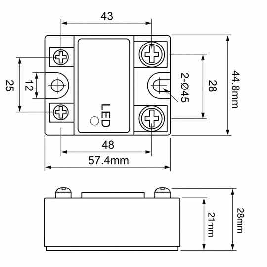
MGR single-phase panel-mount solid state relay dimensional drawing in millimetres
Overall size: 57.4 × 44.8 × 28 mm
CONNECTION / MGR-1 A4840

Load above.
Control below.

Upper terminals 1 and 2 switch the AC load. Lower terminals 3 and 4 accept 70–280 V AC, without polarity. Keep control and load supplies distinct.

MGR-1 A4840 connection illustration
Select to view full size. Confirm the supplied model markings, circuit protection and cooling.
PRINCIPLE / MGR-1 A4840

A command.
A switched load.

The AC control input enables the AC output stage. This is on/off switching, not proportional voltage regulation. The animation is a functional block diagram, not an internal component schematic.
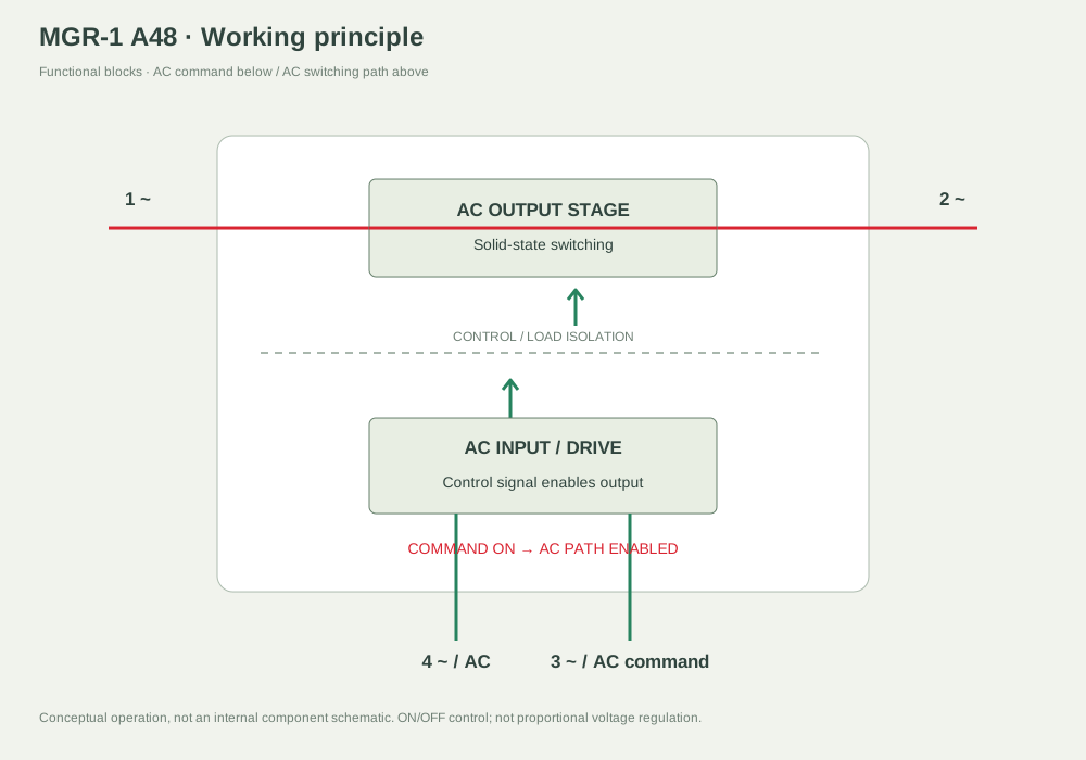
MGR-1 A4840 principle illustration
Select to view full size. Confirm the supplied model markings, circuit protection and cooling.
APPLICATION / MGR-1 A4840

Built into heating equipment.

An AC thermostat commands the relay in an industrial oven control cabinet.
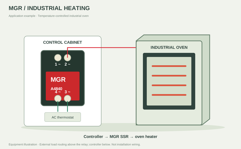
MGR-1 A4840 application illustration
Select to view full size. Confirm the supplied model markings, circuit protection and cooling.

NEED A MODEL-SPECIFIC DATASHEET?

We can help confirm the right A48 relay and thermal setup.

sales@mgrssr.com ↗